Table of Contents


I2C Address conflicts can occur when you have two I2C slave devices with the same fixed address. The easiest way to resolve this situation is by adding another I2C bus to your design. Today I’ll show you a few ways that you can achieve that.
Introduction
The Inter-Integrated Circuit, or I2C, bus has done a lot to simplify the design of systems using microcontrollers, sensors, displays, and microcomputers.
We have worked with the I2C bus many times before here in the DroneBot Workshop. I have done many projects that have used I2C devices and have also covered the bus extensively in three sets of articles and videos:
- Getting started with the I2C Bus – Learning what the bus is, what its origin was and how to use it with the Arduino.
- Building an I2C Slave – Learning how to run an Arduino as either an I2C master or slave and building a custom I2C sensor.
- I2C with Arduino and Raspberry Pi – Communicating between a 5-volt bus Arduino and 3.3-volt bus Raspberry Pi.
You can refer back to those articles if you need to bring yourself up to speed on how the bus works, which would be a good thing to know before delving into today’s content.

Today we are going to look at and resolve one of the problems that we can run into when hooking up multiple devices via I2C – what to do when two devices need to use the same slave address?
It’s not an unsolvable problem, it wouldn’t be a very interesting article if it were! There is actually a very simple solution to the problem and it can be implemented in several different ways.
Address Conflict Problem
Just to make sure that we’re all on the same page let’s take a quick look at what the problem actually is. The following illustrations should serve the purpose.
I2C Address Conflicts
Here is an example of an I2C address conflict:
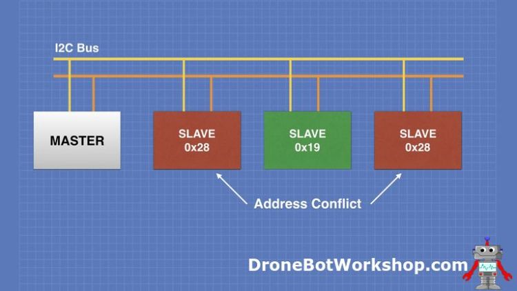
The two I2C slaves have the same address, which is not going to work. At least, most of the time.
In a previous article on Using OLED Displays, I hooked up two small OLED displays that had the same I2C address toa single I2C bus. The result was what you might have expected – both displays showed the same image.
This actually might come in handy if you wanted to put two identical displays on your project. But if you wanted to address each display independently you’re out of luck.
If the slave devices are sensors or require two-way communication with the host then this situation is unworkable.
It’s a basic rule of I2C – every slave device needs to have a unique address.
Setting Slave Addresses
Some slave devices, like displays or sensors, have configurable I2C addresses. This can be in a form of DIP-switches, jumpers, or solder traces to cut or bridge. By setting the address to something unique on our bus address conflicts can be avoided.
This is especially convenient if you want to use two identical devices in your design.
But many I2C devices have a hardcoded address that cannot be modified. How do you handle conflicts between these devices?
Multiple I2C Bus Solution
There is only one real answer – remove one of the devices from the I2C bus and place it on another I2C bus. Then have your bus master connect to both buses.

Which is great, except most microcontrollers like the Arduino only have a single I2C bus. So how do you implement multiple I2C buses with an Arduino?
Turns out you can actually do this two ways:
- Software – Use an alternate I2C library that supports I2C on any Arduino I/O pin.
- Hardware – Use an I2C Multiplexer.
Let’s look at these methods to decide which one is best for our needs.
Software Solutions
The standard Wire Library included with the Arduino IDE allows you to communicate via the I2C bus in either master or slave mode. It uses the pins on the Arduino which are dedicated to I2C, so for example on the Arduino Uno it uses pin A4 as SDA and A5 as SCL.
For all of its great features, it has some shortcomings – Wire does not allow you to have multiple I2C buses, you can only call one instance of it and you can’t redirect your I2C traffic to different pins.
If you want to use multiple I2C buses on the Arduino without any additional hardware then you’ll need to use an alternate library for I2C. There are a few of them that will work, I’ve outlined three of them here.
SoftI2CMaster
- SoftI2CMaster is a simple I2C software implementation
- It comes with three example sketches, including an I2C scanner
You will find SoftI2CMaster on GitHub.
SoftWire
- SoftWire is an I2C software implementation that uses basic Arduino functions to allow any pin to be used for I2C
- It is dependent upon a library called AsyncDelay
- It comes with two example sketches.
You will find SoftWire on GitHub.
Software_I2C
- Software_I2C is another implementation of I2C that is also documented on the Seeedstudio Wiki
- It comes with additional Seeedstudio libraries to use in an example sketch
- It comes with two examples – an I2C scanner and a multiple OLED display sketch.
You will find Software_I2C on GitHub.
Software Libraries Advantages and Disadvantages
All of these libraries are used in place of Wire. For simple I2C implementations, or for adding I2C onto a board that doesn’t have it (such as the ATTiny) these libraries can be invaluable.
But there are also a few disadvantages to using these libraries.
One of the main drawbacks of using these replacement I2C libraries is that many of the sensor and display libraries for I2C devices have a dependency upon the Wire library. And you can’t call Wire in the same sketch that you’re using these libraries with.
You can get around this by editing the sensor or display library and creating a version dependent upon your replacement library. The Seeedstudio library has an OLED display example in which they do exactly that, you can use it as a reference.
Or you can look to hardware to implement additional I2C busses instead.
Hardware Solution
Hardware solutions are more expensive than software solutions of course, but they can have several advantages.
- You can use the standard Wire library and all of your other libraries.
- You won’t need to tie up any additional pins on your Arduino other than SDA and SCL.
And they actually aren’t all that expensive. I’m going to show you how to do it with an easy-to-use module that will cost you less than 10 dollars.
I2C Multiplexer
The device we require is a Multiplexer, which is essentially an electronic switching device.
To be more specific, an I2C Multiplexer that connects to several external I2C busses. When we wish to communicate with a slave device wwe switch to the bus that contains the slave and address it.
Each bus needs to obey the same rules as any I2C bus of course, so slaves can’t have conflicting addresses on individual buses. But as long as you keep your similarly-addressed slaves on different busses you’ll be fine.
TCA9548A I2C Multiplexer Module
We will be using a TCA9548A I2C Multiplexer module form Adafruit. It’s a nicely constructed module that is very simple to use.

This impressive device can switch up to 8 external I2C channels. It has its own I2C address of 0x70, which can be changed using three pins. This allows you to have up to eight of these modules in your design, adding a whopping 64 extra I2C busses!
In our experiments, we will confine ourselves to one device!
The TCA9548A operates on a range of 3 to 5.5 volts, making it suitable for use with both 3.3 and 5-volt logic.
TCA9548A Pinouts
Here are the pinouts of the Adafruit TCA9548A I2C Multiplexer module.

The pins have the following functions:
- Power – the 3 to 5.5 volts DC required by the module. This is normally supplied by the Master controller. Such as the Arduino.
- Ground – All I2C channels need to reference this Ground point.
- I2C Data – The SDA line from the Master
- I2C Clock – the SCL line from the Master.
- Reset – Generally not connected, can be used to reset the multiplexer.
- I2C Address – Pins A0, A1 and A2 can be used to modify the I2C address of the multiplexer. If left disconnected the address will be 0x70.
- Channel 0 – Channel 7 – The external I2C channels. The SDx pins are the SDA connections, and the SCx pins are the SCL clock connections.
The module comes with a couple of rows of Dupont pins that you’ll need to solder.
Display Conflict Demo
To display the use of this module I’m going back to the OLED article and digging out the Temperature and Humidity meter. It uses one of the AM2320 temperature and humidity sensors I recently featured in my article about Measuring Temperature with the Arduino.
In the original sketch, I displayed both temperature and humidity on a single OLED display. But today I’m going to modify it to display its output on two displays, temperature on one and humidity on the other.
This doesn’t sound too difficult until you realize that the OLED displays I’ll be using have fixed I2C addresses. So I can’t use both of them on the same I2C bus and send them different data.
The TCA9548A comes to the rescue! I’ll use it to connect each display onto its own independent I2C bus, so I can address them independently.
Arduino Hookup
Here is how we will hook everything up:

The 5-volt output from the Arduino is used to power all of the external devices – both displays , the AM2320 temperature and humidity sensor and the TCA9548A I2C multiplexer.
The I2C bus from the Arduino is connected to both the multiplexer and the temperature and humidity sensor.
The displays are each connected to independent I2C busses, bus 1 for display 1 and bus 2 for display 2. You could use any two output channels, they are all the same.
Note the use of pullup resistors on the display side. They aren’t required on the Arduino side as the TCA9548A has internal 10K pullup resistors on it’s input, but none on any of its outputs.
You can buy TCA9548A modules from other manufactures that do have strappable pullup resistors on the output channels. Since this module does not have them I used 2.2k pullups, but any value from 2.2 to 20K will work well.
Arduino Code
Here is the sketch I wrote to drive our two independent displays.
|
1 2 3 4 5 6 7 8 9 10 11 12 13 14 15 16 17 18 19 20 21 22 23 24 25 26 27 28 29 30 31 32 33 34 35 36 37 38 39 40 41 42 43 44 45 46 47 48 49 50 51 52 53 54 55 56 57 58 59 60 61 62 63 64 65 66 67 68 69 70 71 72 73 74 75 76 77 78 79 80 81 82 83 84 85 86 87 88 89 90 91 92 93 94 95 96 97 98 99 100 101 102 103 104 105 106 107 108 109 110 111 112 113 |
/* OLED Temperature and Humidity Meter oled-temp-humid-meter-2display.ino Displays results on two 128 x 32 OLED displays Uses TCA9548A I2C Multiplexer Uses AM2320 I2C Temperature and Humidity sensor Uses Adafruit SSD1306 OLED Library Uses Adafruit AM2320 Library Uses Adafruit GFX Graphics Library DroneBot Workshop 2020 https://dronebotworkshop.com */ // Include Wire Library for I2C #include <Wire.h> // Include Adafruit Graphics & OLED libraries #include <Adafruit_GFX.h> #include <Adafruit_SSD1306.h> // Include Adafruit AM2320 Temp Humid Library #include <Adafruit_AM2320.h> // Reset pin not used but needed for library #define OLED_RESET 4 // Create an object for each OLED display Adafruit_SSD1306 display1(OLED_RESET); Adafruit_SSD1306 display2(OLED_RESET); // Define object am2320 Adafruit_AM2320 am2320 = Adafruit_AM2320(); void TCA9548A(uint8_t bus) { Wire.beginTransmission(0x70); // TCA9548A address is 0x70 Wire.write(1 << bus); // send byte to select bus Wire.endTransmission(); } void displayTemp(float tem){ // Clear the display display1.clearDisplay(); //Set the color - always use white despite actual display color display1.setTextColor(WHITE); //Set the font size display1.setTextSize(2); //Set the cursor coordinates display1.setCursor(0,10); display1.print("T: "); display1.print(tem); display1.print(" C"); } void displayHumid(float hum){ // Clear the display display2.clearDisplay(); //Set the color - always use white despite actual display color display2.setTextColor(WHITE); //Set the font size display2.setTextSize(2); //Set the cursor coordinates display2.setCursor(0,10); display2.print("H: "); display2.print(hum); display2.print(" %"); } void setup() { // Start Wire library for I2C Wire.begin(); // Initialize Temp & Humid Sensor am2320.begin(); // Set multiplexer to channel 1 and initialize OLED-0 with I2C addr 0x3C TCA9548A(1); display1.begin(SSD1306_SWITCHCAPVCC, 0x3C); // initialize OLED-1 with I2C addr 0x3C TCA9548A(2); display2.begin(SSD1306_SWITCHCAPVCC, 0x3C); } void loop() { // Delay to allow sensor to stabalize delay(2000); // Read temperature as Celsius float t = am2320.readTemperature(); // Read Humidity float h = am2320.readHumidity(); // Set multiplexer to channel 1 and display temperature TCA9548A(1); displayTemp(t); display1.display(); // Set multiplexer to channel 2 and display temperature TCA9548A(2); displayHumid(h); display2.display(); } |
We start our sketch by including the Arduino Wire Library for I2C. This library is built-in to your Arduino IDE.
We also call two libraries that are not native to the IDE, the Adafruit Graphics Library and the Adafruit Library for the SSD1306 OLED display. You can find and install both of these libraries using your Library Manager.
You’ll also need to find and install the Adafruit AM2320 Library for the temperature and humidity sensor. In addition you’ll want to install the Adafruit Unified Sensor Library, it isn’t called directly from within the sketch but the AM2320 Library requires it.
The OLED display needs a reset pin defined even though it is physically not used, so we comply and define one.
We then create two OLED objects, one to represent each display. We also create an object to represent the temp[erature and humidity sensor.
The TCA9548A function is the key to working with the multiplexer. It operates a lot like a “switch”, changing the multiplexer to direct the data out a specific channel until told otherwise.
The function assumes that the multiplexer has a base address of 0x70, which it will if you don’t modify it using the A0-A2 pins. If you do change the address of the TCA9548A you’ll need to adjust this value to match the new address.
We also define two functions to pass the temperature and humidity value to each OLED display.
In the Setup we start the I2C bus and then initialize the temperature and humidity sensor.
We also need to initialize our two OLED displays, however we need to use the TCA9548A function before we call each one so that we can redirect our I2C data to the correct I2C bus.
In the Loop[ we start with a delay to allow the sensor to stabilize, it requires two seconds between readings.
Next we read the temperature and humidity and assign their values to a couple of floats.
Then we write to each display using the same sequence:
- We call the TCA9548A function and pass the channel (bus) number.
- We call the displayXXX function to display our data on the display
- We refresh the display so it writes the new data.
As long as we call the correct channel our data will be sent to the correct display.
After that we start the loop over again, refreshing both displays every two seconds.
Running the Demo
Load the sketch onto the Arduino.
You should observe the two OLED displays refresh. After two seconds they should both display their data, temperature on one of them and humidity on the other.

Watch it for a while and observe that the data on each display does occasionally change.
You’ve now demonstrated that you can indeed use two displays that have the same I2C address with one Arduino, thanks to the TCA9548A. In fact you could extend this example to have up to eight displays, each one displaying unique data.
Bonus Feature – Mix and Match I2C Voltage Levels
In addition to resolving I2C bus address conflicts the TCA9548A can also be used to solve another I2C design challenge.
The TCA9548A can be powered by either 3.3-volt of 5-volt supplies, generally from the host microcontroller or microcomputer. And all of its external I2C connections are 5-volt tolerant and respond to both 3.3-volt and 5-volt logic.
This means that you can have multiple I2C buses attached to the device and have different logic-levels on those busses.

In this example we are using a 5-volt microcontroller to supply 5-volts to the TCA9548A. Note how we have both 5-volt and 3.3-volt I2C buses attached to the multiplexer, each with its own power supply.
You can “mix and match” I2C busses at different voltage levels throughout the multiplexer. Just be sure to tie all of the power supply grounds together.

The arrangement works equally as well when powering the TCA9548A with a 3.3-volt microcontroller. You always want to power the module using the host controller.
Conclusion
Having two sensors or displays with the same fixed I2C address need not be a show-stopper. By using a multiplexer like the TCA9548A, or an alternate I2C software library, you can implement multiple I2C buses to resolve any address conflicts you encounter.
With its additional capability of using multiple voltage I2C buses, the TCA9548A is my choice for solving bus conflicts.
Parts List
Here are some components that you might need to complete the experiments in this article. Please note that some of these links may be affiliate links, and the DroneBot Workshop may receive a commission on your purchases. This does not increase the cost to you and is a method of supporting this ad-free website.
COMING SOON!
Resources
Code for this Article – The sketch used in this article in a ZIP file.
PDF Version – A PDF Version of the article suitable for printing and using in your own workshop.
Adafruit TCA9548A Multiplexer – The Adafruit module used in this article.
SoftI2CMaster – The SoftI2CMaster Library on GitHub.
SoftWire – The SoftWire Library on GitHub.
Software_I2C – The Software_I2C Library on GitHub.


You provided very useful information. The most important issue is the communication protocol. in this respect; It means there are 8 slave lines in TCA9548A module. If we consider CONNECTING RC522 for these eight (8) pins, what will we follow? Is it necessary to multiplex the MISO AND MOSI lines? thank you so much. I look forward to your return .. I would be glad if you send an e-mail with a drawing on PAPER. 1 You provided very useful information. The most important issue is the communication protocol. in this respect; It means there are 8 slave lines in… Read more »
Thanks so much, it’s a very useful article.
Thanks a lot for your article & vidéos, very clear. I’m on the same kind of issue with 5 OLEDs to manage. When I use your method, I’m not able to control more than 2 OLEDs in the mean time in fact.
I try with and without external 5V supply (better response time with external one).
I put 10k resistors on each SCx/SDx pins as you mention.. but the TCA refuse to manage more than 2 I2C objects. No display…. Are you are of these kind of limitation ? did you try it ? thanks
hi, I need use two tcs34725 on mega, how I do this
can you run 2 INA3221 without the TCA9548A if so do you have an example please.
I need to use multiple APDS9930 sensors and this is the answer to my needs. Thank you/