Table of Contents


Today, we will start with a fantastic radio technology, one that is perfect for IoT projects. Meet LoRa, the inexpensive Long-Range radio system that lets you transmit over long distances without a license.
Introduction
There are many different methods of connecting sensors and actuators in an IoT or remote control installation. WiFi and Bluetooth are pretty common choices and can work well to move large volumes of data, such as video and audio. However, these can be limited in distance, especially when used outdoors.
Cellular technology can be used to send data over wide areas, and for high-bandwidth data like video, it can be a good choice. Of course, a choice like this comes with a higher price tag than simple WiFi or Bluetooth.
But in many IoT and remote control installations, all you really need to send is small bits of data, such as temperature or soil moisture readings. For those applications, there is a much better choice – LoRa.
LoRa
LoRa is a Long Range radio system. It uses an unlicensed radio band and a technology called “Chirp Spread Spectrum” (CSS) to broadcast low-bandwidth data over remarkably large areas. Because of the low power requirements, LoRa devices are inexpensive and consume very little power, so they are ideal for outdoor applications where they can even be solar-powered.

LoRa has a very low bandwidth, typically 300 to 50,000 bits per second. If you are old enough to remember the early dial-up modems, you’re familiar with this data rate! It also is best suited for data that isn’t constantly streaming, but is instead sent in chunks or bursts.
Because of these constrictions, you won’t use LoRa for video or audio; WiFi and Bluetooth are better choices here.
But LoRa is perfect for sensor data, where you just need to send a few bytes of information and can send it periodically. This is a common requirement; things like humidity and soil moisture don’t typically change too rapidly, so you can read those sensors every 10 seconds (or even every minute) and still obtain information that is current enough to be useful.
LoRa has an incredible range for something so low-powered. I tested one of the experiments we did today and achieved a range of over two blocks using simple wire antennas and a transmitter locked in a metal box in my basement (more on that “metal box” later!). With a proper antenna setup, ranges of several miles or kilometers are possible.
The current record for LoRa range was set in the Netherlands in 2020 by Thomas Telkamp, CTO and co-founder of Lacuna Space. He used a balloon to achieve an unbelievable range of 832 kilometers, or 512 miles!
Legalities of Using LoRa
LoRa uses the Industrial, Scientific, and Medical or ISM band, which doesn’t require a license for low-powered devices. You’re operating within the law, providing that you don’t modify your LoRa radio module to increase its output.

There are different frequencies used for the ISM band around the world, so you’ll need to ensure that you are using the frequency that is legal in your area. This Frequency Plans by Country document by The Things Network will help you find the correct frequency for your area.
LoRa itself was originally developed by Cycleo, a French company founded in 2002. They focused on creating a low-cost technology that allowed low-power and long-range communications for short bursts of data.
In 2012, Cycleo was acquired by Semtech Corporation. Semtech continues to develop LoRa and holds the patent for its proprietary modulation technique. To design a radio product with LoRa technology, you’d typically need to purchase chips or modules from Semtech or its partners. But you can use commercial LoRa components for your designs without infringing on patents.
LoRa technology itself is not open-source. However, the protocol built upon LoRa, known as LoRaWAN (Long Range Wide Area Network), is open-source. We will discuss LoRaWAN later in this article.
In short, you don’t need to worry about using LoRa in your designs; the manufacturer of the LoRa radio module you use has already paid Semtech its license fee. Just make sure to use the appropriate ISM band frequency for your location.
LoRa Modules
We will be using a couple of LoRa modules in our experiments today. Actually, they are two versions of the same module, the HopeRF RFM95W.

HopeRF RFM95W
The HopeRF RFM95W, whose specs and pinout are illustrated here, is a tiny LoRa radio module with an SPI interface.

And by “tiny,” I really mean tiny! This module is so small that its pins are spaced closer together than the standard 0.1-inch header spacing common to most modules. As such, you’ll need to find a way of mounting it so that you can use it on a solderless breadboard.
One method is to do it all by hand, using a perfboard. I did this, and it worked well; I used 30 gauge wires to connect the HopeRF RFM95W pins to the pins of a couple of male headers.
You can also buy adapters. I picked up a few that are made by Solder Party. They are intended for use with “FlexyPins” (spring-loaded contact pins) to provide a quick-connect method of using the module, but you can also solder the module on.
Note that this module runs on 3.3-volts and only uses 3.3-volt logic, so take care if interfacing with a 5-volt microcontroller.
Adafruit RFM9x
The Adafruit RFM9x is available in two models:
- The RFM95 LoRa – Use with 868 and 915 MHz LoRa
- The RFM96 LoRa – Use with 433 MHz LoRa
The two modules are identical, aside from their frequency differences.

These modules use the same HopeRF RFM95W LoRa modules described previously, but Adafruit has added a few nice features.
First, there is an onboard voltage regulator. This allows the modules to be powered with any DC supply from 3 to 6 volts. Second, there is onboard logic-level conversion, so the modules are safe with both 3.3 and 5-volt logic devices.
The pins on the module are also spaced the standard 0.1-inch, but it’s a bit of a stretch to call these “solderless breadboard friendly” as the module is too wide for most breadboards. I’ll show you a few ways to accommodate it later in the article.
You also need to figure out how to connect an antenna. If you are using a simple wire antenna, it can be soldered directly to the module. You can also solder a coax cable or an RF connector to the module.
Note that this module is packaged with header pins that are not soldered in. It does NOT come with an RF connector.
Swapping Modules
As these two modules are really the same device in different packaging, they can be used interchangeably in our experiments. Just take note of the differences:
- The HopeRF RFM95W can only use a 3.3-volt power supply.
- The HopeRF RFM95W can only interface with 3.3-volt logic.
- Some of the pin labels are different between the modules.
On that last point, here is a diagram that will let you convert. Keep the other two bullet points in mind if you use the HopeRF RFM95W.
LoRa Antennas
Regardless of which module you choose, you will need an antenna. You should never run a LoRa module without an antenna, it can be damaged by doing this.
An antenna can be as simple as a piece of wire, in fact, that is exactly the type of antenna I used for all of these experiments. Not just any wire will do, though; it has to be the correct length.

The length of the wire depends upon the frequency at which you operate the radio module. For a quarter-wave antenna, the lengths are as follows:
- 433 MHz – 17.31 cm (6.81 inches)
- 868 MHz – 8.63 cm (3.39 inches)
- 915 MHz – 8.19 cm (3.22 inches)
You can also use a commercial antenna, there are several to choose from. Just make sure to select an antenna that is made for the frequency band that you are running your LoRa radio module.

Arduino Hookup
We will do a few experiments using a couple of Arduino Uno boards. The Uno is a 5-volt logic device, so we will use the Adafruit RFM9x module. Remember to purchase the module that suits your local ISM band frequency.

You can use either a classic Uno R3 (or clone) board or one of the new Uno R4 boards for the experiments. The only consideration is the value of the LED dropping resistor; if you use an R4 board, keep this at 330 ohms or higher to avoid drawing too much current from the I/O port. With the classic board, it can be as low as 150 ohms.
You can, of course, use other microcontrollers instead of the Uno for the experiments. You must know the default SPI connections and rewire the circuit accordingly. Also, the G0 pin must be connected to an interrupt-capable pin on the microcontroller. Using a 3.3-volt microcontroller, you could use the HopeRF RFM95W instead of the Adafruit module.
In addition to the Arduino, you’ll also need the Adafruit LoRa module (make sure to choose the correct one for your frequency), a pushbutton switch, an LED, and a dropping resistor for that LED. Wire them up as per the diagram; for the LED, the anode (longer lead) goes to the dropping resistor, and the cathode is grounded.
The LoRa Library for Arduino
As with most Arduino circuits, when you want to work with an external device, there’s a library for that! Actually, there are many LoRa libraries available.
The library we will use is written by Sandeep Mistry and is simply called the LoRa Library. It makes sending and receiving LoRa packets very simple; transmitting packets with this library is about as simple as printing to the serial monitor. It also implements a receive (and transmit) callback system, making coding easy. I’ll illustrate some examples of this in a bit.

You can read the implementation details for the LoRa library on its GitHub page. The API.md document has all the information you’ll need, and the main page shows the wiring information in case you wish to use the library with a different processor or LoRa module.
Installing the LoRa Library
Although you can install the library directly from GitHub, using the Arduino IDE Library Manager is easier.
Open the Library Manager. With the newer IDE 2.x, this can be done by clicking the “library book” icon on the sidebar. You can also open it with the top menu on both versions of the IDE.
Search for “lora”. You’ll get several results, including unrelated libraries with the letters “l o r a” in their name!
Scroll down a bit and look for LoRa by Sandeep Mistry. Click on the Install button to add this library to your Arduino IDE.
The library will also install several example sketches. You can look them over to get a better idea as to how to use it.
Demo 1 – Simple Data Transfer
Our first demo is pretty basic. We will just send a packet of information from one Arduino to the other using LoRa. We will display the packet number on both ends using the serial monitor.
Despite its simplicity, the example will do a fine job illustrating how you use the LoRa library, which I will assume you have already installed in your Arduino IDE.
One of our Arduino boards will be designated the Receiver and the other the Sender. Make note of which is which!
Each board will require its own sketch.
Receiver Sketch
The Arduino designated as the Receiver will use this sketch. Before you load it, please read the notes regarding setting the correct operating frequency:
|
1 2 3 4 5 6 7 8 9 10 11 12 13 14 15 16 17 18 19 20 21 22 23 24 25 26 27 28 29 30 31 32 33 34 35 36 37 38 39 40 41 42 43 44 45 46 47 48 49 50 51 52 53 54 55 56 57 58 59 |
/* LoRa Demo 1 Receiver lora-demo1-receive.ino Receives and displays contents of test packet Requires LoRa Library by Sandeep Mistry - https://github.com/sandeepmistry/arduino-LoRa DroneBot Workshop 2023 https://dronebotworkshop.com */ // Include required libraries #include <SPI.h> #include <LoRa.h> // Define the pins used by the LoRa module const int csPin = 4; // LoRa radio chip select const int resetPin = 2; // LoRa radio reset const int irqPin = 3; // Must be a hardware interrupt pin void setup() { Serial.begin(9600); while (!Serial) ; // Setup LoRa module LoRa.setPins(csPin, resetPin, irqPin); Serial.println("LoRa Receiver Test"); // Start LoRa module at local frequency // 433E6 for Asia // 866E6 for Europe // 915E6 for North America if (!LoRa.begin(915E6)) { Serial.println("Starting LoRa failed!"); while (1) ; } } void loop() { // Try to parse packet int packetSize = LoRa.parsePacket(); if (packetSize) { // Received a packet Serial.print("Received '"); // Read packet while (LoRa.available()) { Serial.print((char)LoRa.read()); } // Print RSSI of packet Serial.print("' with RSSI "); Serial.println(LoRa.packetRssi()); } } |
We start by including the SPI library required for the LoRa module connections. Of course, we also need to include the LoRa library.
We then define constants for some of the pins undefined in the SPI library and for an interrupt-capable pin to allow us to use the modules’ callback functions.
In Setup, we initialize the serial monitor and then set the pins on the LoRa module using the constants we just defined.
The next step is to actually start the module using the command “LoRa.begin(xxxx)”. The “xxxx” refers to the frequency that your LoRa radio module operates, and it needs to be the proper one for your country.
The value is actually the frequency in scientific notation, with the last number representing the number of digits.
- 433E6 – 433 MHz
- 866E6 – 866 MHz
- 915E6 – 915 MHz
The example I’m showing is for 915 MHz, which is good in North and South America. If you require a different frequency, you must edit the sketch with the appropriate value.
After starting the LoRa module successfully, we exit Setup.
In the Loop, we see if we can parse a data packet. If we can, we print to the serial monitor that data is available. We then loop through the data character by character and print it to the serial monitor.
We finish the Loop by printing the signal strength or RSSI of the packet.
Load the sketch to the receive Arduino, and ensure you have edited it for the correct ISM frequency, if necessary.
Sender Sketch
Now, we move on to the sender sketch.
|
1 2 3 4 5 6 7 8 9 10 11 12 13 14 15 16 17 18 19 20 21 22 23 24 25 26 27 28 29 30 31 32 33 34 35 36 37 38 39 40 41 42 43 44 45 46 47 48 49 50 51 52 53 54 55 56 57 58 59 60 61 62 |
/* LoRa Demo 1 Sender lora-demo1-send.ino Sends test packet with packet count Requires LoRa Library by Sandeep Mistry - https://github.com/sandeepmistry/arduino-LoRa DroneBot Workshop 2023 https://dronebotworkshop.com */ // Include required libraries #include <SPI.h> #include <LoRa.h> // Define the pins used by the LoRa module const int csPin = 4; // LoRa radio chip select const int resetPin = 2; // LoRa radio reset const int irqPin = 3; // Must be a hardware interrupt pin // Message counter byte msgCount = 0; void setup() { Serial.begin(9600); while (!Serial) ; // Setup LoRa module LoRa.setPins(csPin, resetPin, irqPin); Serial.println("LoRa Sender Test"); // Start LoRa module at local frequency // 433E6 for Asia // 866E6 for Europe // 915E6 for North America if (!LoRa.begin(915E6)) { Serial.println("Starting LoRa failed!"); while (1) ; } } void loop() { Serial.print("Sending packet: "); Serial.println(msgCount); // Send packet LoRa.beginPacket(); LoRa.print("Packet "); LoRa.print(msgCount); LoRa.endPacket(); // Increment packet counter msgCount++; // 5-second delay delay(5000); } |
The sender sketch starts the same as the receiver one, adding one variable, a message counter.
The Setup is identical to the last sketch. Be sure to edit it for the correct LoRa ISM frequency.
The Loop illustrates how easy it is to send data using the LoRa Library.
We start the Loop by printing both a message and the counter value to the Serial monitor. The counter value is what we will be sending as a message to the receiver.
We then do a LoRa.beginPacket() to start forming a LoRa data packet. After that, we do a series of LoRa.print() statements, each one adds data to the packet.
Finally, we call LoRa.endPacket(). This finishes forming the packet and also sends it.
We finish the Loop by incrementing the message counter and delaying for five seconds. Remember, with LoRa, you only send bursts of data. You can reduce this delay if you’re impatient!
Load this sketch up to the sender Arduino, again noting that it is set for the correct frequency.
Now run both Arduino’s. If you are using the newer IDE 2.x, you can open two instances of it and use two serial monitors, as I did here.

You should see the packet number on the sender incrementing and the same number being received on the other Arduino.
Experiment by changing the values used in the send data; try adding more LoRa.print() statements and observe the results.
This illustrates how simple it is to send and receive data using LoRa. Now let’s do something with that data!
Demo 2 – One-way Remote Control
As we have wired pushbuttons and LEDs up to both Arduino’s, you can probably guess what we will do next!
Yes, indeed, we will use a pushbutton to control a remote LED! In this first example, we will just do it in one direction, so one Arduino is the Receiver, and one is the Sender again. You can designate the same ones as last time or switch them around; they are wired up the same!
Receiver Sketch
Here is the Receiver side sketch:
|
1 2 3 4 5 6 7 8 9 10 11 12 13 14 15 16 17 18 19 20 21 22 23 24 25 26 27 28 29 30 31 32 33 34 35 36 37 38 39 40 41 42 43 44 45 46 47 48 49 50 51 52 53 54 55 56 57 58 59 60 61 62 63 64 65 66 67 68 69 70 71 72 73 74 75 76 77 78 79 80 81 82 83 84 85 86 87 88 89 90 91 92 |
/* LoRa Demo 2 Receiver lora-demo2-receive.ino Receive LoRa signal to control LED Requires LoRa Library by Sandeep Mistry - https://github.com/sandeepmistry/arduino-LoRa DroneBot Workshop 2023 https://dronebotworkshop.com */ // Include required libraries #include <SPI.h> #include <LoRa.h> // Define the pins used by the LoRa module const int csPin = 4; // LoRa radio chip select const int resetPin = 2; // LoRa radio reset const int irqPin = 3; // Must be a hardware interrupt pin // LED connection const int ledPin = 5; // Receive message variables String contents = ""; String buttonPress = "button pressed"; bool rcvButtonState; void setup() { // Set LED as output pinMode(ledPin, OUTPUT); Serial.begin(9600); while (!Serial) ; // Setup LoRa module LoRa.setPins(csPin, resetPin, irqPin); Serial.println("LoRa Receiver"); // Start LoRa module at local frequency // 433E6 for Asia // 866E6 for Europe // 915E6 for North America if (!LoRa.begin(915E6)) { Serial.println("Starting LoRa failed!"); while (1) ; } } void loop() { // Try to parse packet int packetSize = LoRa.parsePacket(); // Received a packet if (packetSize) { Serial.print("Received packet '"); // Read packet while (LoRa.available()) { contents += (char)LoRa.read(); } // Print RSSI of packet Serial.print("' with RSSI "); Serial.println(LoRa.packetRssi()); Serial.println(contents); // Toggle button state if (contents.equals(buttonPress)) { rcvButtonState = !rcvButtonState; } // Drive LED if (rcvButtonState == true) { digitalWrite(ledPin, HIGH); Serial.println("led on"); } else { digitalWrite(ledPin, LOW); Serial.println("led off"); } // Clear contents contents = ""; } } |
On the receiver side, we start like all our sketches have so far. We also define a few other variables:
- A constant for the LED pin
- A variable for the received message contents.
- A string with the contents “button pressed”. This is the text string we are trying to match.
- A boolean to hold the state of the receive button toggle.
The only thing we do in the Setup that is different is to set the LED pin as an output. Once again, ensure you have configured your LoRa.begin statement for the correct frequency.
In the Loop, we read the incoming data packet as before. But this time, we compare the contents with the saved string. If they match, we toggle the button state boolean, which sets the LED status.
We finish by clearing the contents of the incoming message variable.
Sender Sketch
And, of course, the sender side sketch:
|
1 2 3 4 5 6 7 8 9 10 11 12 13 14 15 16 17 18 19 20 21 22 23 24 25 26 27 28 29 30 31 32 33 34 35 36 37 38 39 40 41 42 43 44 45 46 47 48 49 50 51 52 53 54 55 56 57 58 59 60 61 62 63 64 65 66 67 68 69 70 |
/* LoRa Demo 2 Sender lora-demo2-send.ino Use pushbutton to control LED on receiver Requires LoRa Library by Sandeep Mistry - https://github.com/sandeepmistry/arduino-LoRa DroneBot Workshop 2023 https://dronebotworkshop.com */ // Include required libraries #include <SPI.h> #include <LoRa.h> // Define the pins used by the LoRa module const int csPin = 4; // LoRa radio chip select const int resetPin = 2; // LoRa radio reset const int irqPin = 3; // Must be a hardware interrupt pin // Message counter byte msgCount = 0; // Pushbutton variables int buttonPin = 8; int sendButtonState; void setup() { // Set pushbutton as input pinMode(buttonPin, INPUT_PULLUP); Serial.begin(9600); while (!Serial) ; // Setup LoRa module LoRa.setPins(csPin, resetPin, irqPin); Serial.println("LoRa Sender"); // Start LoRa module at local frequency // 433E6 for Asia // 866E6 for Europe // 915E6 for North America if (!LoRa.begin(915E6)) { Serial.println("Starting LoRa failed!"); while (1) ; } delay(1000); } void loop() { // Get pushbutton state sendButtonState = digitalRead(buttonPin); // Send packet if button pressed if (sendButtonState == LOW) { // Send packet LoRa.beginPacket(); LoRa.print("button pressed"); LoRa.endPacket(); msgCount++; Serial.print("Sending packet: "); Serial.println(msgCount); delay(500); } } |
The sender sketch also builds upon the last sketch, adding two new variables.
- An integer to represent the pin connected to the pushbutton.
- Another integer, this one represents the state of the pushbutton.
The only thing added to the Setup is to define the pushbutton pin as an input using the internal pull-up resistors.
In the Loop, we read the pushbutton and hold its state in the integer variable. If the state is LOW, we know the button has been pressed, so we compose a packet using the LoRa library and send it to the receiver. The packet contains the message “button pressed”, the same string we are on the lookout for on the receive side.
We add a half-second delay to debounce the pushbutton before exiting and repeating the Loop.

Load up the two sketches and observe them in action. You can also watch the serial monitors for each board. You should be able to control the receiver LED using the pushbutton on the sender.
Demo 3 – Two-way Remote Control
Of course, we have LEDs and pushbuttons on both Arduino boards, so we will want to control them both ways. To do that, we will introduce a few new concepts that will improve our coding and performance.
Receive Callback
In the following sketch, we’ll be using a “receive callback function,” which we have used before when coding for other communications technologies.
A “callback” is a signal produced when an event happens; the signal is used to trigger a function, very much like an interrupt. A “receive callback” is initiated whenever data is received by the LoRa module. It’s actually the reason we require an interrupt-capable pin to interface with the LoRa module’s GPIO pin.
We treat a callback like an interrupt by writing a function to handle it. So, in this case, we will write a function that is called every time a packet of data is received. As with an interrupt handler, it’s best not to put too much code into a callback function.
Two-way Remote Sketch
In this demonstration, we’ll use the same sketch on both ends. There is a modification you can make to one sketch if you wish; more on that in a bit.
|
1 2 3 4 5 6 7 8 9 10 11 12 13 14 15 16 17 18 19 20 21 22 23 24 25 26 27 28 29 30 31 32 33 34 35 36 37 38 39 40 41 42 43 44 45 46 47 48 49 50 51 52 53 54 55 56 57 58 59 60 61 62 63 64 65 66 67 68 69 70 71 72 73 74 75 76 77 78 79 80 81 82 83 84 85 86 87 88 89 90 91 92 93 94 95 96 97 98 99 100 101 102 103 104 105 106 107 108 109 110 111 112 113 114 115 116 117 118 119 120 121 122 123 124 125 126 127 128 129 130 131 132 133 134 135 136 137 138 139 140 141 142 143 144 145 146 147 148 149 150 151 152 153 154 155 156 157 158 159 160 161 |
/* LoRa Demo 3 lora-demo3.ino Bi-directional LED control (duplex communications) Requires LoRa Library by Sandeep Mistry - https://github.com/sandeepmistry/arduino-LoRa sendMessage & onReceive functions based upon "LoRaDuplexCallback" code sample by Tom Igoe DroneBot Workshop 2023 https://dronebotworkshop.com */ // Include required libraries #include <SPI.h> #include <LoRa.h> // Define the pins used by the LoRa module const int csPin = 4; // LoRa radio chip select const int resetPin = 2; // LoRa radio reset const int irqPin = 3; // Must be a hardware interrupt pin // LED connection const int ledPin = 5; // Outgoing message variable String outMessage; // Message counter byte msgCount = 0; // Receive message variables String contents = ""; String buttonPress = "button pressed"; bool rcvButtonState; // Source and destination addresses byte localAddress = 0xBB; // address of this device byte destination = 0xFF; // destination to send to // Pushbutton variables int buttonPin = 8; int sendButtonState; void setup() { // Set pushbutton as input pinMode(buttonPin, INPUT_PULLUP); // Set LED as output pinMode(ledPin, OUTPUT); Serial.begin(9600); while (!Serial) ; Serial.println("LoRa Duplex with callback"); // Setup LoRa module LoRa.setPins(csPin, resetPin, irqPin); // Start LoRa module at local frequency // 433E6 for Asia // 866E6 for Europe // 915E6 for North America if (!LoRa.begin(915E6)) { Serial.println("Starting LoRa failed!"); while (1) ; } // Set Receive Call-back function LoRa.onReceive(onReceive); // Place LoRa in Receive Mode LoRa.receive(); Serial.println("LoRa init succeeded."); } void loop() { // Get pushbutton state sendButtonState = digitalRead(buttonPin); // Send packet if button pressed if (sendButtonState == LOW) { // Compose and send message outMessage = buttonPress; sendMessage(outMessage); delay(500); // Place LoRa back into Receive Mode LoRa.receive(); } } // Send LoRa Packet void sendMessage(String outgoing) { LoRa.beginPacket(); // start packet LoRa.write(destination); // add destination address LoRa.write(localAddress); // add sender address LoRa.write(msgCount); // add message ID LoRa.write(outgoing.length()); // add payload length LoRa.print(outgoing); // add payload LoRa.endPacket(); // finish packet and send it msgCount++; // increment message ID } // Receive Callback Function void onReceive(int packetSize) { if (packetSize == 0) return; // if there's no packet, return // Read packet header bytes: int recipient = LoRa.read(); // recipient address byte sender = LoRa.read(); // sender address byte incomingMsgId = LoRa.read(); // incoming msg ID byte incomingLength = LoRa.read(); // incoming msg length String incoming = ""; // payload of packet while (LoRa.available()) { // can't use readString() in callback, so incoming += (char)LoRa.read(); // add bytes one by one } if (incomingLength != incoming.length()) { // check length for error Serial.println("error: message length does not match length"); return; // skip rest of function } // If the recipient isn't this device or broadcast, if (recipient != localAddress && recipient != 0xFF) { Serial.println("This message is not for me."); return; // skip rest of function } // If message is for this device, or broadcast, print details: Serial.println("Received from: 0x" + String(sender, HEX)); Serial.println("Sent to: 0x" + String(recipient, HEX)); Serial.println("Message ID: " + String(incomingMsgId)); Serial.println("Message length: " + String(incomingLength)); Serial.println("Message: " + incoming); Serial.println("RSSI: " + String(LoRa.packetRssi())); Serial.println("Snr: " + String(LoRa.packetSnr())); Serial.println(); // Toggle button state if (incoming.equals(buttonPress)) { rcvButtonState = !rcvButtonState; } // Drive LED if (rcvButtonState == true) { digitalWrite(ledPin, HIGH); Serial.println("led on"); } else { digitalWrite(ledPin, LOW); Serial.println("led off"); } } |
The sketch starts by declaring all of the variables we have used already. We then declare a local and destination address, and it’s here that you can make modifications if you wish.
In this sketch, we introduce the concept of assigning an address to each device. This is broadcast as part of the LoRa packet. It’s not a “LoRa address,” just something we include in our self-defined packet.
The address of “FF” is the broadcast address and will work on any device. So, the sketch does not necessarily need to be modified, as it sends out to “FF”. But you can experiment with assigning different addresses to both units. The experiment gets even better when you have three or more units!
Before we look at the Loop, let’s move to the bottom of the sketch to examine the two functions, which are key to understanding how this all works.
The first one, sendMessage, just sends a LoRa packet with the specified message. The packet is formed using LoRa library statements. It includes both the source and destination address, as well as the message and message length. The length is used as a simple error-checking method on the receive side.
The next function is the receive callback.
The function begins by checking to see if the packet is valid. If it is, it extracts the dates from it and checks the data length to see if it matches what it received.
Assuming that all the data is good, the function checks the address to see if it is a broadcast packet or one with the local address. If it isn’t, the function exits, as this message is not for us.
If the message is for us, we toggle the button state variable and use it to drive the LED, as we did in the last sketch.
Now, back to the Loop!
The Loop is almost identical to the one we used in the last sketch. We read the button, and if it has been pressed, we send a packet and then delay a bit to debounce the pushbutton. The differences are that we use a function to send data this time and intentionally put the LoRa module in receive mode when we finish sending.

Load the sketch to both modules; you can assign them different addresses to experiment with. You should be able to use either pushbutton to toggle the opposite Arduino board’s LED.
LoRa with MicroPython
Up until now, all the experiments we have done have been using the Arduino IDE and C++. But we can also use other languages to work with LoRa.
So, we will use the Raspberry Pi Pico running MicroPython for the next experiment. You can substitute any other MicroPython-capable board if you wish.
Here is how we will hook up the Pico:

Installing MicroPython on the Pico
Before we get started, you’ll need to grab two Raspberry Pi Pico boards. You can use a Pico, a Pico W, or both. Our experiment won’t make use of the WiFi on the Pico W.
Once you have your boards, you must install the latest version of the MicroPython interpreter onto them. It’s a pretty easy process, illustrated in the following animation:

You can get the latest version of the MicroPython firmware for the Raspberry Pi Pico from the official MicroPython website.
Once you have MicroPython installed, you will need a way of working with it. There are several good editors; a popular one and one that is ideal for the Pico is the Thonny IDE. You can get it for Windows, Mac, or Linux.
ulora MicroPython Library & Examples
Once again, we will rely upon the services of a library to do all the “heavy lifting” and make writing scripts for LoRa very simple.
The ulora library for MicroPython by Martyn Wheeler is a port of the LoRa Library for Python used with the Raspberry Pi microcomputers. In addition to the Pico, ulora can be used on other MicroPython-capable microcontrollers, such as the ESP32.
You can clone the library from GitHub or download the ZIP and extract it. Once you have the library files, you can examine the three relevant ones.
- ulora.py – The library itself.
- client.py – The MIcroPython script for the client side.
- server.py – The MicroPython script for the server side.
These scripts are ready to run on our Pico boards. You need to distribute them as follows:
Server – ulora.py & server.py
Client – ulora.py & client.py
You can use the Thonny IDE to copy the files onto the Pico boards. Just open them from your computer and save them on the Pico.
MicroPython Client Script
Both scripts are pretty simple. We will begin with the client script, which sends a test message to the server every ten seconds.
|
1 2 3 4 5 6 7 8 9 10 11 12 13 14 15 16 17 18 19 20 21 22 |
from time import sleep from ulora import LoRa, ModemConfig, SPIConfig # Lora Parameters RFM95_RST = 27 RFM95_SPIBUS = SPIConfig.rp2_0 RFM95_CS = 5 RFM95_INT = 28 RF95_FREQ = 915.0 RF95_POW = 20 CLIENT_ADDRESS = 1 SERVER_ADDRESS = 2 # initialise radio lora = LoRa(RFM95_SPIBUS, RFM95_INT, CLIENT_ADDRESS, RFM95_CS, reset_pin=RFM95_RST, freq=RF95_FREQ, tx_power=RF95_POW, acks=True) # loop and send data while True: lora.send_to_wait("This is a test message", SERVER_ADDRESS) print("sent") sleep(10) |
The script starts with imports from the time and ulora libraries. We then define the connections to the LoRa module, as well as the module parameters.
Note that on line 9, the LoRa ISM frequency is defined. Make sure that you edit this line for the correct frequency.
After that, we initialize the LoRa radio module. Note the wealth of parameters you can pass to the module, including its transmit power.
Then, we simply create a loop with a 10-second delay, during which we send our LoRa packet.
Run this script on one Raspberry Pi Pico to send out LoRa data.
MicroPython Server Script
Now for the script on the server side. On this side, we will receive the data from our client.
|
1 2 3 4 5 6 7 8 9 10 11 12 13 14 15 16 17 18 19 20 21 22 23 24 25 26 27 28 29 30 31 |
from time import sleep from ulora import LoRa, ModemConfig, SPIConfig # This is our callback function that runs when a message is received def on_recv(payload): print("From:", payload.header_from) print("Received:", payload.message) print("RSSI: {}; SNR: {}".format(payload.rssi, payload.snr)) # Lora Parameters RFM95_RST = 27 RFM95_SPIBUS = SPIConfig.rp2_0 RFM95_CS = 5 RFM95_INT = 28 RF95_FREQ = 868.0 RF95_POW = 20 CLIENT_ADDRESS = 1 SERVER_ADDRESS = 2 # initialise radio lora = LoRa(RFM95_SPIBUS, RFM95_INT, SERVER_ADDRESS, RFM95_CS, reset_pin=RFM95_RST, freq=RF95_FREQ, tx_power=RF95_POW, acks=True) # set callback lora.on_recv = on_recv # set to listen continuously lora.set_mode_rx() # loop and wait for data while True: sleep(0.1) |
We are using the same libraries we used on the client script. The parameters are also the same; make sure you edit the RF95_FREQ for your local ISM band frequency.
This script uses a callback similar to the one we used in the last Arduino sketch. In this case, the callback prints the message contents, signal strength, and signal-to-noise ratio.
The rest of the script initializes the LoRa radio module and places it into listen mode.

Load this script to the second Pico and use the shell in the Thonny IDE to observe the printout. You should see data, signal strength, and signal-to-noise ratio, updating every ten seconds.
Multiple Node LoRa – Remote Environment Sensors
The following project can be viewed in many ways:
- As an experiment illustrating data-gathering techniques using LoRa.
- As a practical project.
- As the basis for an advanced data-gathering project.
The project itself is pretty basic. It’s a controller with an OLED display displaying the temperature and humidity from two remote sensors. Of course, it uses LoRa for communications, so the remote sensors can be very remote indeed!
By itself, this is a useful application or learning tool. But it can also serve as the basis of a more advanced data gathering project, collecting more than just temperature and humidity data.
Let’s review how it works. Once you understand its operation, you can modify it for any data-gathering application.

Principle of Operation
The operation of the system can be broken down into bullet points:
- There is a central controller based on an ESP32
- There are two remote sensors based on Arduino Uno boards.
- The remote devices have DHT22 temperature and humidity sensors.
- The controller polls each board sequentially, once every three seconds.
- The remote responds with a temperature and humidity value when polled.
- After each response, the remote initiates a 2-second timeout to give the DHT22 time to stabilize. During this time, it will ignore requests for new data.
- The central controller displays the temperature and humidity readings on the OLED display. It alternates the display once every three seconds, displaying the data in two different formats.
- If the central controller loses connection with a remote, it displays a series of question marks.
The code relies upon receive callbacks and code in the loop.
Remote Sensor Operation
This flowchart illustrates the operation of the Receive Callback and Loop code for the remote sensors. This is the code that runs on the Arduino Uno boards.

The receive callback is initiated whenever we receive a message. We check to see if it was meant for us, if it isn’t, then we exit the callback.
If the message is for us, we update the “message variable”. This is just the packet number received from the controller. We use this variable to see if the request is new.
In the Loop, we check that message variable and compare it to the last one we examined. If it differs, then we know it is a new request. We read the DHT22 sensor and send the temperature and humidity values to the controller in a LoRa packet. Then, we apply a 2-second delay.
The 2-second delay is for the DHT22 sensor, which needs it to stabilize. If we get a new request while the delay is still on, we will ignore it until we finish.
Remote Wiring
Since we already have two Arduino Uno boards wired to Adafruit RFM9x LoRa radio modules, we can reuse them for this project. We need to add a DHT22 (AM2302) temperature and humidity sensor to pin 9, and that’s it.
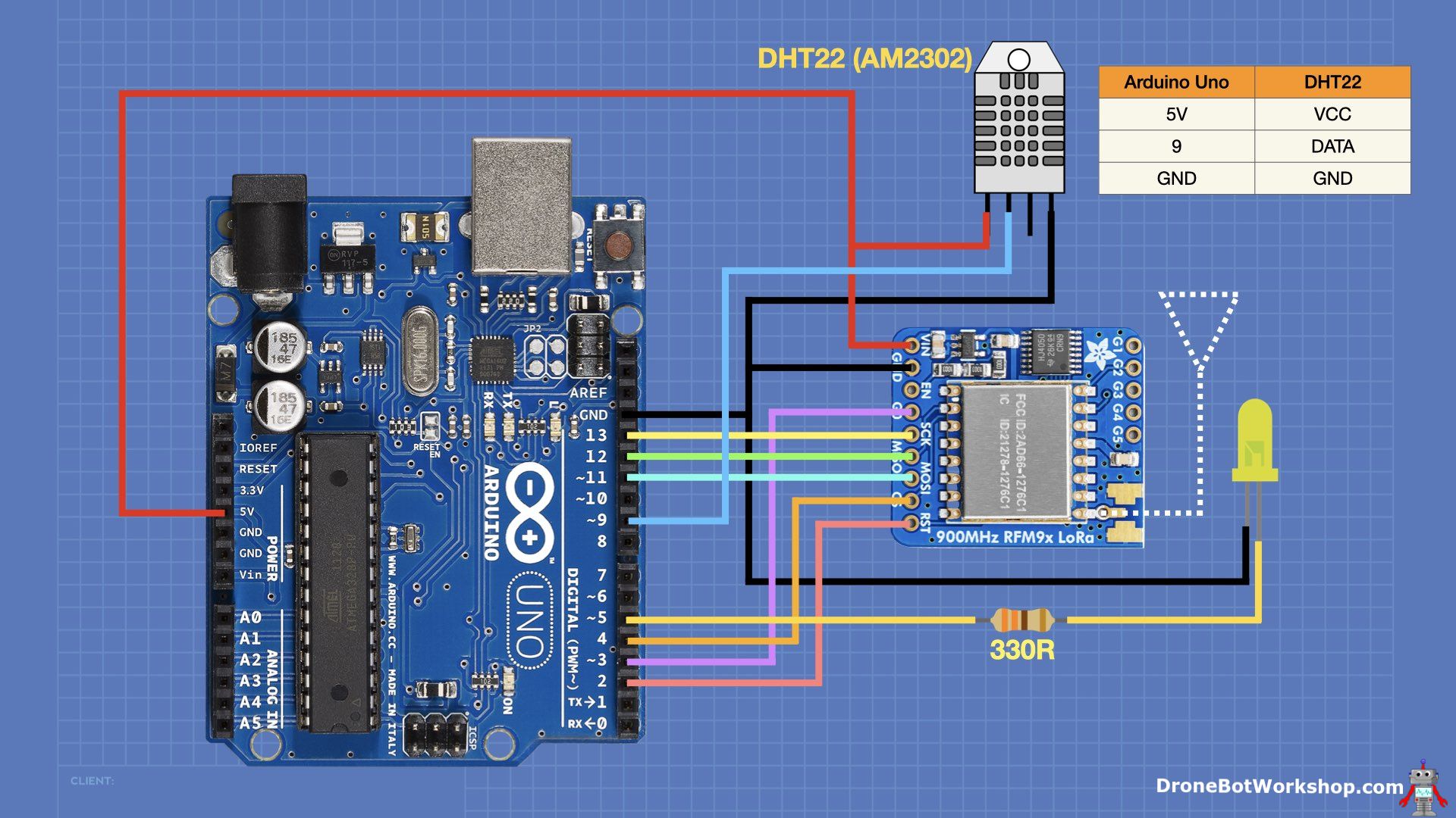
The LED will be used again in this project, but the pushbutton is unused. You can leave it there, which is what I did. It is removed from the wiring diagram only for clarity.
Remote Sensor Sketch (Arduino Uno & DHT22)
The LoRa remote temperature and humidity sensor sketch requires a library for the DHT22 that you may not have installed in your Arduino IDE. You will need to install the DHTLib Library by Rob Tillaart, which you can find in your Arduino IDE Library Manager.
|
1 2 3 4 5 6 7 8 9 10 11 12 13 14 15 16 17 18 19 20 21 22 23 24 25 26 27 28 29 30 31 32 33 34 35 36 37 38 39 40 41 42 43 44 45 46 47 48 49 50 51 52 53 54 55 56 57 58 59 60 61 62 63 64 65 66 67 68 69 70 71 72 73 74 75 76 77 78 79 80 81 82 83 84 85 86 87 88 89 90 91 92 93 94 95 96 97 98 99 100 101 102 103 104 105 106 107 108 109 110 111 112 113 114 115 116 117 118 119 120 121 122 123 124 125 126 127 128 129 130 131 132 133 134 135 136 137 138 139 140 141 142 143 144 145 146 147 148 149 150 151 152 153 154 155 156 157 158 159 160 161 162 163 164 165 166 167 168 169 170 171 172 |
/* LoRa Multi-Sensor Temperature & Humidity Monitor - Sensor lora-temp-humid-sensor.ino Remote Node for LoRa Temperature and Humidity Monitor Uses Arduino Uno, Adafruit RFM9x LoRa Module & DHT22 Temp/Humid sensor Sends Temperature and Humidity data to central controller Requires LoRa Library by Sandeep Mistry - https://github.com/sandeepmistry/arduino-LoRa Requires DHTlib Library by Rob Tillaart DroneBot Workshop 2023 https://dronebotworkshop.com */ // Include required libraries #include <SPI.h> #include <LoRa.h> #include <dht.h> // DHT22 Connection #define DHTPIN 9 // LED connection (if used) const int ledPin = 5; // DHT Temp/Humid sensor object dht DHT; // Define the pins used by the LoRa module const int csPin = 4; // LoRa radio chip select const int resetPin = 2; // LoRa radio reset const int irqPin = 3; // Must be a hardware interrupt pin // Outgoing message variable String outMessage; // Controller data variable String inMessage; // Previous value Controller data variable String inMessageOld; // Outgoing Message counter byte msgCount = 0; // Source and destination addresses byte localAddress = 0xAA; // address of this device (must be unique, 0xAA or 0xBB) byte destination = 0x01; // destination to send to (controller = 0x01) // Receive Callback Function void onReceive(int packetSize) { if (packetSize == 0) return; // if there's no packet, return // Read packet header bytes: int recipient = LoRa.read(); // recipient address byte sender = LoRa.read(); // sender address byte incomingMsgId = LoRa.read(); // incoming msg ID byte incomingLength = LoRa.read(); // incoming msg length String incoming = ""; // payload of packet while (LoRa.available()) { // can't use readString() in callback, so incoming += (char)LoRa.read(); // add bytes one by one } if (incomingLength != incoming.length()) { // check length for error Serial.println("error: message length does not match length"); return; // skip rest of function } // If the recipient isn't this device or broadcast, if (recipient != localAddress && recipient != 0xFF) { Serial.println("This message is not for me."); return; // skip rest of function } // If we are this far then this message is for us // Update the controller data variable inMessage = incoming; } // Send LoRa Packet void sendMessage(String outgoing) { LoRa.beginPacket(); // start packet LoRa.write(destination); // add destination address LoRa.write(localAddress); // add sender address LoRa.write(msgCount); // add message ID LoRa.write(outgoing.length()); // add payload length LoRa.print(outgoing); // add payload LoRa.endPacket(); // finish packet and send it msgCount++; // increment message ID } void setup() { Serial.begin(9600); while (!Serial) ; // Set LED as output (if used) pinMode(ledPin, OUTPUT); // Setup LoRa module LoRa.setPins(csPin, resetPin, irqPin); // Start LoRa module at local frequency // 433E6 for Asia // 866E6 for Europe // 915E6 for North America if (!LoRa.begin(915E6)) { Serial.println("Starting LoRa failed!"); while (1) ; } // Set Receive Call-back function LoRa.onReceive(onReceive); // Place LoRa in Receive Mode LoRa.receive(); Serial.println("LoRa init succeeded."); } void loop() { // Run only if requested if (inMessage != inMessageOld) { // New message variable, take reading and send to controller int readData = DHT.read22(DHTPIN); // Reads the data from the sensor float t = DHT.temperature; // Gets the values of the temperature float h = DHT.humidity; // Gets the values of the humidity // Printing the results on the serial monitor Serial.print("Temperature = "); Serial.print(t); Serial.print(" *C "); Serial.print(" Humidity = "); Serial.print(h); Serial.println(" % "); // Format the outgoing message string String outMsg = ""; outMsg = outMsg + t + ":" + h; // Send data as LoRa packet sendMessage(outMsg); // Print controller variables Serial.print("Old Controller Data = "); Serial.println(inMessageOld); Serial.print("New Controller Data = "); Serial.println(inMessage); // Update the"old" data variable inMessageOld = inMessage; // Place LoRa in Receive Mode LoRa.receive(); // Optional 2-second LED pulse (remark out if LED not used) digitalWrite(ledPin, HIGH); Serial.println("led on"); // 2-second delay for DHT sensor delay(2000); // Optional 2-second LED pulse (remark out if LED not used) digitalWrite(ledPin, LOW); Serial.println("led off"); } } |
The sketch begins by including the required libraries. We also define the pins for the DHT22 sensor and LoRa module connections.
We define a number of strings to hold message variables. One for the outgoing message and two for the incoming message. The incoming message is the packet number sent by the controller, and we will save the most recent one in a variable so we can use it to determine if the controller request is fresh.
Note line 46 with the local address. You will need to change this on one remote sensor. Keep one sensors code at 0xAA, and change the second one to 0xBB. This is the sensor’s identity code and is the ONLY difference between the two remote sensors.
The Receive Callback function onReceive checks the validity of the incoming data packet. If it is a valid packet intended for us, then we update the local message variable with the packet contents.
The sendMessage function is identical to what we saw in the two-way LED control example; it just uses a number of LoRa library functions to build and send a LoRa packet.
In the Setup, we initialize the LoRa Module, set the LED as an output, and put LoRa into receive mode.
In the Loop, we constantly scan for the value of the message variable and compare it to the one we have. If it matches, then there is no new request from the controller. But if there is a mismatch, we take the temperature and humidity readings and print them to the serial monitor.
We then format a string to send to the controller, essentially a colon-delimited string with temperature and humidity. We send that string using the sendMessage function.
After that, we implement a 2-second delay, during which we will turn on the LED. This results in the LED flashing on for two seconds periodically, which makes a good indication that the sensor is connected to the controller.
As a recap, before you load the sketch to an Arduino, check the following:
- The LoRa frequency (line 109)
- The Sensor Address (line 46)
After verifying that, load the sketch to the first Arduino. Unplug it, plug in the second one, change the address on line 46, and upload the edited sketch to the second Arduino.
Controller Operation
Now, it’s time to focus on the controller, which is based on an ESP32. You can use any ESP32 module, and we are not using WiFi or Bluetooth, so you could also use another microcontroller. If you do change processors, you’ll need to note the default SPI and I2C connections, as both are used in this design.
The following diagram shows the information flow in both the Receive Callback and Loop of the controller code:

When the Receive Callback is initiated, we check to see if the message is for us. If it isn’t, we exit the callback.
If the message is for us, we identify the sender to know which remote unit is sending us data. We then update the local temperature and humidity variables for that sensor.
We also update a timestamp variable for that sensor; this tells us how fresh the data is. Then, we exit the callback.
In the Loop, we check the sensor and timestamp variables. If the data is fresh, we update the OLED display with it; if it is old, we change the display to indicate that a remote sensor is offline.
We wait for 3 seconds and then change the display format. We also send a request to the first sensor for new data.
We then wait three seconds and send a second request. Then the Loop ends, and we do it all over again.
This method lets us stagger the data requests to the sensors, so the chances of data returning from the sensors colliding are nil. It also allows the sensors plenty of time to execute that 2-second delay the DHT22 needs.
Controller Wiring
The controller uses an ESP32, an OLED display, and the HopeRF RFM95W module. Its hookup is shown here:

You can substitute the Adafruit LoRa module for the HopeRF one; they are operationally equivalent.
Controller Sketch (ESP32 & OLED)
The controller sketch requires the Adafruit SSD1306 and GFX libraries. You can install these from the Library Manager if you need to. They are pretty common libraries, so you may already have one or both already installed.
|
1 2 3 4 5 6 7 8 9 10 11 12 13 14 15 16 17 18 19 20 21 22 23 24 25 26 27 28 29 30 31 32 33 34 35 36 37 38 39 40 41 42 43 44 45 46 47 48 49 50 51 52 53 54 55 56 57 58 59 60 61 62 63 64 65 66 67 68 69 70 71 72 73 74 75 76 77 78 79 80 81 82 83 84 85 86 87 88 89 90 91 92 93 94 95 96 97 98 99 100 101 102 103 104 105 106 107 108 109 110 111 112 113 114 115 116 117 118 119 120 121 122 123 124 125 126 127 128 129 130 131 132 133 134 135 136 137 138 139 140 141 142 143 144 145 146 147 148 149 150 151 152 153 154 155 156 157 158 159 160 161 162 163 164 165 166 167 168 169 170 171 172 173 174 175 176 177 178 179 180 181 182 183 184 185 186 187 188 189 190 191 192 193 194 195 196 197 198 199 200 201 202 203 204 205 206 207 208 209 210 211 212 213 214 215 216 217 218 219 220 221 222 223 224 225 226 227 228 229 230 231 232 233 234 235 236 237 238 239 240 241 242 243 244 245 246 247 248 249 250 251 252 253 254 255 256 257 258 259 260 261 262 263 264 265 266 267 268 269 270 271 272 273 274 275 276 277 278 279 280 281 282 283 284 285 286 287 288 289 290 291 292 293 294 295 296 297 298 299 300 301 302 303 304 305 306 307 308 309 310 311 312 313 314 315 316 317 318 319 320 321 |
/* LoRa Multi-Sensor Temperature and Humidity Monitor - Controller lora-temp-humid-control.ino Central Controller for LoRa Temperature and Humidity Monitor Uses ESP32, RFM95W LoRa & SSD1306 I2C OLED Display Displays Temperature and Humidity readings from remote sensors Requires LoRa Library by Sandeep Mistry - https://github.com/sandeepmistry/arduino-LoRa Requires Adafruit GFX and SSD1306 libraries DroneBot Workshop 2023 https://dronebotworkshop.com */ // Include required libraries #include <SPI.h> #include <LoRa.h> #include <Wire.h> #include <Adafruit_GFX.h> #include <Adafruit_SSD1306.h> // Define the pins used by the LoRa module const int csPin = 5; // LoRa radio chip select const int resetPin = 14; // LoRa radio reset const int irqPin = 2; // Must be a hardware interrupt pin // Source and sensorAddress1 addresses byte localAddress = 0x01; // Address of this device (Controller = 0x01) byte sensorAddress1 = 0xAA; // Address of Sensor 1 byte sensorAddress2 = 0xBB; // Address of Sensor 2 // OLED parameters #define SCREEN_WIDTH 128 // OLED display width, in pixels #define SCREEN_HEIGHT 64 // OLED display height, in pixels #define OLED_RESET -1 // Reset pin # (or -1 if sharing Arduino reset pin) #define SCREEN_ADDRESS 0x3C // Change if required // Define display object Adafruit_SSD1306 display(SCREEN_WIDTH, SCREEN_HEIGHT, &Wire, OLED_RESET); // Remote temperature and humidity variables // Data variable String remoteData1 = "TT.tt:HH.hh"; String remoteData2 = "TT.tt:HH.hh"; // Sensor 1 String remoteTemp1; String remoteHumid1; // Sensor 2 String remoteTemp2; String remoteHumid2; // Remote sensor time variables unsigned long currentActive1 = millis(); unsigned long currentActive2 = millis(); const long checkInterval = 12500; // 12.5 second sensor check interval // Outgoing Message counter byte msgCount = 0; // FUNCTION newDisplay() - Refresh the display with new data void newDisplay(String temp1, String humid1, String temp2, String humid2, int displayOrder) { // Print display header display.clearDisplay(); display.setTextColor(WHITE); display.setTextSize(1); display.setCursor(0, 0); display.print("REMOTE TEMP & HUMID"); // If displayOrder = 1 then reverse display order if (displayOrder == 1) { // Remote Sensor 2 is first display.setTextSize(2); display.setCursor(0, 16); display.print("T2: "); display.setCursor(38, 16); display.print(temp2); display.print("C"); display.setCursor(0, 34); display.print("H2: "); display.setCursor(38, 34); display.print(humid2); display.print("%"); // Node 1 in smaller font display.setTextSize(1); display.setCursor(0, 55); display.print("T1: "); display.setCursor(18, 55); display.print(temp1); display.print("C"); display.setCursor(60, 55); display.print("H1: "); display.setCursor(78, 55); display.print(humid1); display.print("%"); } else { // Remote Sensor 1 1 is first display.setTextSize(2); display.setCursor(0, 16); display.print("T1: "); display.setCursor(38, 16); display.print(temp1); display.print("C"); display.setCursor(0, 34); display.print("H1: "); display.setCursor(38, 34); display.print(humid1); display.print("%"); // Node 2 in smaller font display.setTextSize(1); display.setCursor(0, 55); display.print("T2: "); display.setCursor(18, 55); display.print(temp2); display.print("C"); display.setCursor(60, 55); display.print("H2: "); display.setCursor(78, 55); display.print(humid2); display.print("%"); } display.display(); } // FUNCTION getValue() - Extract value from delimited string String getValue(String data, char separator, int index) { int found = 0; int strIndex[] = { 0, -1 }; int maxIndex = data.length() - 1; for (int i = 0; i <= maxIndex && found <= index; i++) { if (data.charAt(i) == separator || i == maxIndex) { found++; strIndex[0] = strIndex[1] + 1; strIndex[1] = (i == maxIndex) ? i + 1 : i; } } return found > index ? data.substring(strIndex[0], strIndex[1]) : ""; } // FUNCTION onReceive() - Receive call-back function void onReceive(int packetSize) { if (packetSize == 0) return; // if there's no packet, return // read packet header bytes: int recipient = LoRa.read(); // recipient address byte sender = LoRa.read(); // sender address byte incomingMsgId = LoRa.read(); // incoming msg ID byte incomingLength = LoRa.read(); // incoming msg length String incoming = ""; // payload of packet while (LoRa.available()) { // can't use readString() in callback, so incoming += (char)LoRa.read(); // add bytes one by one } if (incomingLength != incoming.length()) { // check length for error Serial.println("error: message length does not match length"); return; // skip rest of function } // if the recipient isn't this device if (recipient != localAddress) { Serial.println("This message is not for me."); return; // skip rest of function } // Determine sender, then update data variables and time stamps if (sender == sensorAddress1) { //Remote Sensor 1 remoteData1 = incoming; currentActive1 = millis(); } else if (sender == sensorAddress2) { //Remote Sensor 2 remoteData2 = incoming; currentActive2 = millis(); } } // FUNCTION sendMessage() - Send LoRa Packet void sendMessage(String outgoing, byte target) { LoRa.beginPacket(); // start packet LoRa.write(target); // add sensorAddress1 address LoRa.write(localAddress); // add sender address LoRa.write(msgCount); // add message ID LoRa.write(outgoing.length()); // add payload length LoRa.print(outgoing); // add payload LoRa.endPacket(); // finish packet and send it msgCount++; // increment message ID } // FUNCTION getValues() - get the temperature and humidity values from the data variables void getValues() { // Check to see if sensors have reported in recently // Get current timestamp value unsigned long currentMillis = millis(); // See if we have exceeded the check interval time limit // Sensor 1 if (currentMillis - currentActive1 <= checkInterval) { // Data is good, extract temp ahd humid remoteTemp1 = getValue(remoteData1, ':', 0); // Remote 1 Temperature remoteHumid1 = getValue(remoteData1, ':', 1); // Remote 1 Humidity } else { remoteTemp1 = "??.??"; remoteHumid1 = "??.??"; } // Sensor 2 if (currentMillis - currentActive2 <= checkInterval) { // Data is good, extract temp ahd humid remoteTemp2 = getValue(remoteData2, ':', 0); // Remote 1 Temperature remoteHumid2 = getValue(remoteData2, ':', 1); // Remote 1 Humidity } else { remoteTemp2 = "??.??"; remoteHumid2 = "??.??"; } } void setup() { Serial.begin(9600); while (!Serial) ; // SSD1306_SWITCHCAPVCC = generate display voltage from 3.3V internally if (!display.begin(SSD1306_SWITCHCAPVCC, SCREEN_ADDRESS)) { Serial.println(F("SSD1306 allocation failed")); for (;;) ; // Don't proceed, loop forever } // Clear the display buffer display.clearDisplay(); display.display(); // Refresh OLED newDisplay("XX.XX", "XX.XX", "XX.XX", "XX.XX", 0); // Setup LoRa module LoRa.setPins(csPin, resetPin, irqPin); Serial.println("LoRa Receiver Test"); // Start LoRa module at local frequency // 433E6 for Asia // 866E6 for Europe // 915E6 for North America if (!LoRa.begin(915E6)) { Serial.println("Starting LoRa failed!"); while (1) ; } LoRa.onReceive(onReceive); LoRa.receive(); Serial.println("LoRa init succeeded."); } void loop() { // Get latest data values getValues(); Serial.print("Temp 1: "); Serial.print(remoteTemp1); Serial.print(" - Humid 1: "); Serial.println(remoteHumid1); Serial.print("Temp 2: "); Serial.print(remoteTemp2); Serial.print(" - Humid 2: "); Serial.println(remoteHumid2); // Update OLED newDisplay(remoteTemp1, remoteHumid1, remoteTemp2, remoteHumid2, 0); // Delay 3 seconds to hold display delay(3000); // Send message to remote 1 String outMsg1 = ""; outMsg1 = outMsg1 + msgCount; sendMessage(outMsg1, sensorAddress1); // Place LoRa back into Receive Mode LoRa.receive(); // Refresh the data values getValues(); // Update OLED - reverse display newDisplay(remoteTemp1, remoteHumid1, remoteTemp2, remoteHumid2, 1); // Delay 3 seconds to hold display delay(3000); // Send message to remote 2 String outMsg2 = ""; outMsg2 = outMsg2 + msgCount; sendMessage(outMsg2, sensorAddress2); // Place LoRa back into Receive Mode LoRa.receive(); } |
Aside from the Adafruit libraries, which are for the OLED display, we require the SPI, I2C, and LoRa libraries.
After defining the LoRa module connections, we define the local and remote addresses as follows:
- Local Address – 0x01
- Sensor 1 Address – 0xAA
- Sensor 2 Address – 0xBB
Don’t change these values. They need to match the values on the remote sensors.
We define some parameters for the OLED display and then create an object to represent it.
We create two data variable strings, one for each sensor. Likewise, we also create variables to store the temperature and humidity values for booth remote sensors.
Now for a few functions! The first one uses the temperature and humidity data to format and display data on the OLED. It can output in two modes:
- Mode 1 – Sensor 1 Large Font, Sensor 2 Small Font
- Mode 2 – Sensor 2 Large Font, Sensor 1 Small Font
The next function, getValue, extracts the characters from the colon-delimited string. It extracts them individually, and you specify if you want to extract the characters before or after the colon.
The receive Callback does the usual check to the packet. If it is a valid one for us, then it checks the sender’s address to see who sent it. It then updates the data variable and timestamp for that sensor.
The sendMessage function is the same one we have used before.
The getValues function uses the data variables to get the actual temperature and humidity values. It also tests the data age; if it is too old, it changes the display to all question marks.
A lot of the Setup is to initialize the OLED display with all “X”, which will be what we see when we start the controller. We also do the usual LoRa setup; again, remember to set the frequency correctly for your local ISM band.
In the Loop we get the values for temperature and humidity and print them on the display in mode 1. We then wait three seconds, send out a LoRa message for sensor 1 data, and change display to mode 2. After another three seconds, we send out a request for sensor 2 data and end the Loop.
Once you have all the code loaded, give it a try. The controller should boot up with all “X” displays, followed by temperature and humidity from both sensors. The sensors should have a flashing LED.

Try and see how far you can get for range. I was able to get two blocks with one of my remote sensors in the freezer in my basement! All this with a 3-inch wire antenna!

Conclusion
LoRa is an amazing technology that will really make gathering data from remote sensors simple.
The LoRa radio modules I used today are by no means the only ones available to experimenters, and new modules and microcontrollers with integrated LoRa are being introduced frequently. LoRa is here to stay!
Keep your eyes glued to this website and the YouTube channel, as the next time we visit LoRa we will be working with LoRaWAN, a protocol that allows for sophisticated and long-range LoRa networking.
Until then, enjoy working with the experiments. See what kind of range you can get with your LoRa setup, and let us all know in the comments!
Parts List
Here are some components you might need to complete the experiments in this article. Please note that some of these links may be affiliate links, and the DroneBot Workshop may receive a commission on your purchases. This does not increase the cost to you and is a method of supporting this ad-free website.
HopeRF RFM95W LoRa Module Amazon
Adafruit RFM95 LoRa Module (868 & 915 MHz) Adafruit
Adafruit RFM96 LoRa Module (433 MHz) Adafruit
Resources
Code Samples – All the code used in this article in one easy-to-use ZIP file!
Article PDF – A PDF version of this article in a ZIP file.
MicroPython for Raspberry Pi Pico – latest build of the MicroPython interpreter for the Raspberry Pi Pico and Pico W.
Thonny IDE for MicroPython – The Thonny IDE for Windows, Mac, and Linux.
U-LoRa Library for MicroPython – U-LoRa MicroPython Library.
Arduino LoRa Library – Arduino LoRa Library.
HopeRF RFM95 Module – Documentation for HopeRF RFM95 LoRa radio module.
Adafruit RFM95W Module – Documentation for Adafruit RFM95x modules.
LoRa Frequency Plans by Country – Find the correct ISM frequency for your location.
LoRa by Semtech – Official LoRa provider.


This was a very interesting topic. I have done some reading into LoRa, and thought the only multi-node transmission was with LoRaWan, but to see you do it with the last experiment was exciting. One (multi-part question), can more nodes be added (obviously with adding the required addresses in both the Remote and Controller sketches) and increase the time delay to account for the added nodes with the last part of removing the two part data display on the OLED and just display the last data received? Sounds like this should be a fairly simple sketch modification. Or does the… Read more »
I would suspect that you can add several nodes, the two-node experiment was more of a demo.
What Gage wire are you using for antenna ?
I’m using 22 gauge solid wire
Thanks !
This is more exciting. Can we use Esp32 for temperature sensor as well.?
How far are two blocks? Sorry I’m from China, we don’t use imperial units and blocks to describe distances.
A city block is approximately 1/10 mile but it certainly varies from city to city.
A few times on the server the ‘on_recv’ function will be called twice on a single sent from the client; 6 times in 255 times. That’s the first why?
After 255 messages sent by the client (so from messages 256 and up), the server is calling the ‘on_recv’ function 4 times for each single sent by the client.
I know 256 is a ‘magic’ number, but why from that number and up 4 times for each single sent by the client?
It appears that in Europe the LoRa standards specify a ‘maximum duty cycle’ depending on the frequency/band being used and appears to be between 0.1 and 1.0%. I take this to mean that to be compliant in Europe, a single LoRa module should not be transmitting for more than 0.1 – 1.0% of the time. Does any one know whether this is correct?
Excellent article once again… thank you !
One bit I am stuck on… if LORA has AES128 encryption, how does one use that? Sure ly the two modules transmitting encrypted data would have to share a key or else anyone with another lora module could intercept the data and ignore the destination address?
I wanted to inform people that the link to the HopeRF RFM95W module seems to have changed to https://www.hoperf.com/product/Infinite/RFM95W.html
Hope that helps
Can I change the channel for example 433000000 to 433200000?
hi, can I send a command from the assembly (ESP8266+lora is my receiver)
to the assembly (arduino nano +lora+gps is my transmitter ) yes, I would like to send a signal from the receiver and wake up the transmitter so that the transmitter starts transmitting data to the same receiver on the access point’s web page ESP8266
I wired my HopeRF RFM95W on my Rasp. Pico (MicroPython), and see that it is sending.
On my SDR, I see the signals very clear at 868Mhz.
But I have trouble with LoRa-Communication between different products / brands.
HopeRF RFM95W <–> Heltec LoRa V3
PySense LoRa <–> HopeRF RFM95W
Is the Client- and Server-Address in the Python example needed for communication?
Or is there some broadcast mode, where everyone can receive what I’m sending?