
Table of Contents


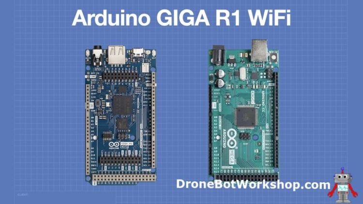
What looks like an Arduino Mega 2560, has 76 I/O ports, WiFi and Bluetooth, 16-bit Analog to Digital Converters, USB A and USB-C ports, and a Real Time Clock? It’s the Arduino GIGA, the most powerful Arduino yet!
Today we will take a look at the GIGA and at some of its more interesting features.
Introduction
With features like those already mentioned, plus many more, plus a dual-core microcontroller with mind-boggling specifications, the GIGA only resembles the Mega 2560 in form factor. It inherits its features from the Arduino Pro line of IoT controllers, specifically the Portenta series of microcontroller modules.
The GIGA has many features we haven’t seen in hobbyist-level microcontroller boards, and it will find use within IoT devices, process control applications, and robotics. Its two superfast cores can even run MicroPython and C++ independently, allowing for some very advanced designs.

Let’s explore this amazing new microcontroller in depth.
Arduino GIGA R1 WiFi
The Arduino GIGA R1 WiFi board is packaged in a small cardboard box. The board includes a small antenna and a plastic carrier that conveniently holds the board during experimentation.
Arduino GIGA Specifications
Here is an outline of the specifications of the Arduino GIGA:
Microcontroller
The Arduino GIGA is based on a STM32H747XIH6 Microcontroller. This microcontroller has two cores:
- 32-bit Arm® Cortex®-M7 core with double-precision FPU and L1 cache up to 480 MHz
- 32-bit Arm® 32-bit Cortex®-M4 core with FPU up to 240 MHz
The STM32H747XIH6 includes a full set of DSP instructions and a Memory Protection Unit (MPU).
WiFi & Bluetooth
The Arduino GIGA uses a Murata® 1DX Wi-Fi/Bluetooth Module with the following capabilities:
- Wi-Fi 802.11b/g/n 65 Mbps
- Bluetooth Low Energy (version 5.X via Cordio stack, version 4.2 via Arduino Stack)
Memory
There are three memory storage devices on the Arduino GIGA, with a total of five memory areas.
- STM32H747XI – 2MB Flash & 1 MB RAM
- AT25SF128A-MHB-T – 16 MB NOR Flash
- AS4C4M16SA – 8 MB SDRAM
Input/Output
The Arduino GIGA has a wide variety of I/O pins:
- Digital I/O Pins: 76
- Analog input pins: 12
- PWM pins: 12
- Analog output pins (DAC0/DAC1): 2
- USB Host: USB 2.0 A
- USB Peripheral: USB-C®
- Logic level: 3.3V
- VRTC: To power the RTC while the board is off
- OFF pin: To turn off the board
Communication
There are also many communications options on the GIGA:
- 4x UART
- 3x I2C
- 2x SPI
- 1x CAN (an external transceiver is required)
USB Ports
There are two USB connectors on the Arduino GIGA:
- USB-A – USB Host for keyboards, mice, and USB mass storage devices.
- USB-C – Programming and HID (emulates mice and keyboards)
Arduino GIGA Pinout
The GIGA has the same form factors as the Arduino Mega 256o and Arduino Due. The pinouts are compatible with its predecessors, but it should be noted that the GIGA is a 3.3-volt logic device and is not 5-volt tolerant.

There are also additional; connectors for a DSI display and an Arducam camera. These connectors can also be used as additional I/O ports.


Getting Started with the GIGA
Before you can start using the GIGA, you’ll need to set up your Arduino IDE.
I’m illustrating the process with the current IDE 2.0, but you may also use the older IDE 1.8 if you wish.
Installing the Boards Manager
The first step you’ll need to take is installing the Arduino GIGA Boards Manager. You can do that by opening the Boards Manager in your Arduino IDE and searching for “GIGA”.
If you don’t get any results, you will need to update your Boards Manager. You likely received a message about there being updates for it when you opened the IDE.
Once you find the GIGA board manager, click on it to install it.
When the installation is finished, the Arduino GIGA should now be one of the boards available to you. Select it and look at the example code that Arduino provides with the board manager when it is installed.
Resolving the LINUX DFU Problem
I struggled to get the IDE to work correctly with the GIGA under Ubuntu Linux. I soon found out that all of my Linux computers experienced the same error, a complaint about the licensing level of the DFU (Device Firmware Update) connection.

A thread on the Arduino Forum discusses this problem and offers solutions. While I did not experience the problem using Microsoft Windows, apparently, some people have. If you do, then you should check out the thread, as you may find your answer there.
Under Linux, the solution seems to be to add a “rules” file and then update the system to use it. Here is how I fixed the issue on my computers:
-
- Close Arduino IDE
- Open File Manager
- Navigate to /etc/udev/rules.d
- Open a Terminal
- Type the following:
- sudo nano 60-arduino-renesas.rules
-
- Nano editor opens
- Enter the following text:
- SUBSYSTEMS==”usb”, ATTRS{idVendor}==”2341″, MODE:=”0666″
-
- Press Ctrl-W to Write the file
- Press Ctrl-X to Exit
- You can do a ls to list the files to confirm that the new file exists.
- At the command line, type the following two lines (press enter after each line):
- udevadm trigger
- udevadm control –reload-rules
- Restart the Arduino IDE
- Try to upload a sketch – it should work now!

I have created a “Cheat Sheet” that you can use to simplify inputting the commands. I illustrated its use in the video that accompanies this article. It’s in the ZIP file with the code.
Using the Real-Time Clock
The Arduino GIGA has a built-in Real Time Clock (RTC), along with provisions for a backup battery. We can use the clock in our Arduino code.
Battery Backup
There are three solder pads on the side of the Arduino GIGA board that are labeled as follows:
- OFF – Connecting this pin to ground will power down the GIGA. You can use this to implement a power switch.
- GND – A ground connection.
- VRTC – Connection for a backup battery for the clock.
You can connect a battery between the GND and VRTC pins, observing polarity, of course.

While Arduino does not specify which battery to use, they refer to it as a “coin cell”. I tried with a 3-volt battery, and it worked correctly.

Manual RTC Code
The first example we will try is a simple sketch that sets the clock manually. You can use it as the basis for a more advanced program. This code was provided by Arduino.
|
1 2 3 4 5 6 7 8 9 10 11 12 13 14 15 16 17 18 19 20 21 22 23 24 25 26 27 28 29 30 31 32 33 34 35 36 37 38 39 40 41 42 43 44 45 46 |
/* Arduino GIGA Real Time Clock - Manual giga-rtc-manual.ino Demonstrates Arduino GIGA real time clock operation Prints time to serial monitor Code provided by Arduino */ #include "mbed.h" #include <mbed_mktime.h> constexpr unsigned long printInterval{ 1000 }; unsigned long printNow{}; void setup() { Serial.begin(9600); //RTCset(); } void loop() { if (millis() > printNow) { Serial.print("System Clock: "); Serial.println(getLocaltime()); printNow = millis() + printInterval; } } void RTCset() // Set cpu RTC { tm t; t.tm_sec = (0); // 0-59 t.tm_min = (52); // 0-59 t.tm_hour = (14); // 0-23 t.tm_mday = (18); // 1-31 t.tm_mon = (11); // 0-11 "0" = Jan, -1 t.tm_year = ((22) + 100); // year since 1900, current year + 100 + 1900 = correct year set_time(mktime(&t)); // set RTC clock } String getLocaltime() { char buffer[32]; tm t; _rtc_localtime(time(NULL), &t, RTC_4_YEAR_LEAP_YEAR_SUPPORT); strftime(buffer, 32, "%Y-%m-%d %k:%M:%S", &t); return String(buffer); } |
It’s a pretty basic sketch and does not require additional libraries.
The function RTCset creates a data structure that sets the time. It is set for December 18, 2022 at 14:52. You can, of course, change this, but we are just using this as a test.
RTCset is called in the Setup, so every time the GIGA is reset, the clock will revert to its original date and time.
Load the sketch to your GIGA and run it. You will see the time displayed every second on the serial monitor.
You can test out the operation of the clock and backup battery using this sketch, which I did in the video accompanying this article. Here is how you go about doing this:
- Connect a battery to the VRTC and GND terminals. You will probably have to solder on a connector (I used Dupont pins) to do this.
- Run the sketch and observe the output.
- Remove and replace the USB-C cable. This will power off and on the board and reset the time.
- Now edit the sketch and remove the call to RTCset. This will prevent the sketch from setting the time. You should see the time increment from its last reading instead of reverting to the original time.
- Pull the USB-C, wait a few seconds, and put it back in. The clock reading should persist, as the battery backed up the RTC.
- Try the above without the battery. The clock will revert to January 1, 1970, which is the first date in Linux time.
This is a great way to become familiar with the clock’s operation.
WiFi RTC Code
Another way to set the time on the RTC is to get a time reference from an Internet Time Server. These servers use Network Time Protocol (NTP) and can be referenced to the cesium atomic clock that sets the world’s standard time.
Here is a sketch to do just that. It has a second file, arduino_secrets.h, which you will use to enter your network credentials.
|
1 2 3 4 5 6 7 8 9 10 11 12 13 14 15 16 17 18 19 20 21 22 23 24 25 26 27 28 29 30 31 32 33 34 35 36 37 38 39 40 41 42 43 44 45 46 47 48 49 50 51 52 53 54 55 56 57 58 59 60 61 62 63 64 65 66 67 68 69 70 71 72 73 74 75 76 77 78 79 80 81 82 83 84 85 86 87 88 89 90 91 92 93 94 95 96 97 98 99 100 101 102 103 104 105 106 107 108 109 110 111 112 113 114 115 116 117 118 119 120 121 122 123 124 125 126 127 128 129 130 131 132 133 134 135 136 137 138 139 140 141 142 143 144 145 146 147 148 149 150 151 152 153 154 155 156 157 158 159 160 161 162 163 164 165 166 167 168 169 170 171 172 173 174 175 176 177 178 179 180 181 182 183 184 |
/* Arduino GIGA Real Time Clock - WiFi giga-rtc-wifi.ino Demonstrates Arduino GIGA real time clock operation using Internet time source Prints time to serial monitor Code provided by Arduino */ /* Udp NTP Client Get the time from a Network Time Protocol (NTP) time server Demonstrates use of UDP sendPacket and ReceivePacket For more on NTP time servers and the messages needed to communicate with them, see http://en.wikipedia.org/wiki/Network_Time_Protocol created 4 Sep 2010 by Michael Margolis modified 9 Apr 2012 by Tom Igoe modified 28 Dec 2022 by Giampaolo Mancini This code is in the public domain. */ #include <WiFi.h> #include <WiFiUdp.h> #include <mbed_mktime.h> int status = WL_IDLE_STATUS; #include "arduino_secrets.h" ///////please enter your sensitive data in the Secret tab/arduino_secrets.h char ssid[] = SECRET_SSID; // your network SSID (name) char pass[] = SECRET_PASS; // your network password (use for WPA, or use as key for WEP) int keyIndex = 0; // your network key index number (needed only for WEP) unsigned int localPort = 2390; // local port to listen for UDP packets // IPAddress timeServer(162, 159, 200, 123); // pool.ntp.org NTP server constexpr auto timeServer{ "pool.ntp.org" }; const int NTP_PACKET_SIZE = 48; // NTP timestamp is in the first 48 bytes of the message byte packetBuffer[NTP_PACKET_SIZE]; // buffer to hold incoming and outgoing packets // A UDP instance to let us send and receive packets over UDP WiFiUDP Udp; constexpr unsigned long printInterval{ 1000 }; unsigned long printNow{}; void setup() { // Open serial communications and wait for port to open: Serial.begin(9600); while (!Serial) { ; // wait for serial port to connect. Needed for native USB port only } // check for the WiFi module: if (WiFi.status() == WL_NO_SHIELD) { Serial.println("Communication with WiFi module failed!"); // don't continue while (true) ; } // attempt to connect to WiFi network: while (status != WL_CONNECTED) { Serial.print("Attempting to connect to SSID: "); Serial.println(ssid); // Connect to WPA/WPA2 network. Change this line if using open or WEP network: status = WiFi.begin(ssid, pass); // wait 10 seconds for connection: delay(10000); } Serial.println("Connected to WiFi"); printWifiStatus(); setNtpTime(); } void loop() { if (millis() > printNow) { Serial.print("System Clock: "); Serial.println(getLocaltime()); printNow = millis() + printInterval; } } void setNtpTime() { Udp.begin(localPort); sendNTPpacket(timeServer); delay(1000); parseNtpPacket(); } // send an NTP request to the time server at the given address unsigned long sendNTPpacket(const char* address) { memset(packetBuffer, 0, NTP_PACKET_SIZE); packetBuffer[0] = 0b11100011; // LI, Version, Mode packetBuffer[1] = 0; // Stratum, or type of clock packetBuffer[2] = 6; // Polling Interval packetBuffer[3] = 0xEC; // Peer Clock Precision // 8 bytes of zero for Root Delay & Root Dispersion packetBuffer[12] = 49; packetBuffer[13] = 0x4E; packetBuffer[14] = 49; packetBuffer[15] = 52; Udp.beginPacket(address, 123); // NTP requests are to port 123 Udp.write(packetBuffer, NTP_PACKET_SIZE); Udp.endPacket(); } unsigned long parseNtpPacket() { if (!Udp.parsePacket()) return 0; Udp.read(packetBuffer, NTP_PACKET_SIZE); const unsigned long highWord = word(packetBuffer[40], packetBuffer[41]); const unsigned long lowWord = word(packetBuffer[42], packetBuffer[43]); const unsigned long secsSince1900 = highWord << 16 | lowWord; constexpr unsigned long seventyYears = 2208988800UL; const unsigned long epoch = secsSince1900 - seventyYears; set_time(epoch); #if defined(VERBOSE) Serial.print("Seconds since Jan 1 1900 = "); Serial.println(secsSince1900); // now convert NTP time into everyday time: Serial.print("Unix time = "); // print Unix time: Serial.println(epoch); // print the hour, minute and second: Serial.print("The UTC time is "); // UTC is the time at Greenwich Meridian (GMT) Serial.print((epoch % 86400L) / 3600); // print the hour (86400 equals secs per day) Serial.print(':'); if (((epoch % 3600) / 60) < 10) { // In the first 10 minutes of each hour, we'll want a leading '0' Serial.print('0'); } Serial.print((epoch % 3600) / 60); // print the minute (3600 equals secs per minute) Serial.print(':'); if ((epoch % 60) < 10) { // In the first 10 seconds of each minute, we'll want a leading '0' Serial.print('0'); } Serial.println(epoch % 60); // print the second #endif return epoch; } String getLocaltime() { char buffer[32]; tm t; _rtc_localtime(time(NULL), &t, RTC_FULL_LEAP_YEAR_SUPPORT); strftime(buffer, 32, "%Y-%m-%d %k:%M:%S", &t); return String(buffer); } void printWifiStatus() { // print the SSID of the network you're attached to: Serial.print("SSID: "); Serial.println(WiFi.SSID()); // print your board's IP address: IPAddress ip = WiFi.localIP(); Serial.print("IP Address: "); Serial.println(ip); // print the received signal strength: long rssi = WiFi.RSSI(); Serial.print("signal strength (RSSI):"); Serial.print(rssi); Serial.println(" dBm"); } |
This is another Arduino-provided sketch, although there were some errors at the beginning (it didn’t reference the arduino_secrets.h file correctly). The version below has been corrected:
This is actually an adaptation of a much older sketch that can be used with most microcontrollers. Two of its principal functions are the sendNTPpacket function, which formats data to send to the NTP server, and the parseNtpPacket function, which formats the received data.
Running the sketch should produce an output on the serial monitor that shows the correct time.
Working with USB-A
The feature of the new Arduino GIGI R1 WiFi board that I am the most intrigued by has to be the USB-A connector. This connector allows you to use a USB mouse, keyboard, or mass-storage device with your Arduino, opening up many possible applications.

Let’s perform a few experiments with the USB-A connector.
USB Drive with FAT32
You will need a USB mass storage device, such as a USB thumb drive, to perform these experiments.
The drive must be formatted with FAT32; this is important, as the Arduino library we are using can only read FAT32-formatted devices.
Verbatim has a utility that can be used to format FAT32 devices over 32GB. Unfortunately, this is only available for Microsoft Windows.
It also would be a good idea to name your mass storage device “usb”. The sketches we are using are provided by Arduino and, unfortunately, they hard-coded the USB device name instead of making it a variable. If you don’t want to edit the files, you can just name your device “usb”; it’s much easier!
Read USB Directory
The first sketch we will check out is one provided by Arduino that reads the directory from a FAT32-formatted USB mass storage device.
The sketch Arduino provided initially worked, but it broke when they updated the library and also renamed it. The following sketch, and the others in this section, reflect that name change.
|
1 2 3 4 5 6 7 8 9 10 11 12 13 14 15 16 17 18 19 20 21 22 23 24 25 26 27 28 29 30 31 32 33 34 35 36 37 38 39 40 41 42 43 44 45 46 47 48 49 50 51 52 53 54 55 56 57 58 59 60 61 62 63 64 65 66 67 68 69 70 71 72 73 74 75 76 77 78 79 80 81 82 83 84 85 86 87 |
/* Arduino GIGA USB File List Example giga-usb-dir.ino Demonstrates Arduino GIGA USB file listing Lists files of a FAT32 formatted USB mass storage device Requires Arduino_USBHostMbed5 Library Code provided by Arduino */ #include <DigitalOut.h> #include <FATFileSystem.h> #include <Arduino_USBHostMbed5.h> USBHostMSD msd; mbed::FATFileSystem usb("usb"); void setup() { Serial.begin(115200); pinMode(PA_15, OUTPUT); //enable the USB-A port digitalWrite(PA_15, HIGH); while (!Serial) ; Serial.println("Starting USB Dir List example..."); // if you are using a Max Carrier uncomment the following line // start_hub(); while (!msd.connect()) { //while (!port.connected()) { delay(1000); } Serial.print("Mounting USB device... "); int err = usb.mount(&msd); if (err) { Serial.print("Error mounting USB device "); Serial.println(err); while (1) ; } Serial.println("done."); char buf[256]; // Display the root directory Serial.print("Opening the root directory... "); DIR* d = opendir("/usb/"); Serial.println(!d ? "Fail :(" : "Done"); if (!d) { snprintf(buf, sizeof(buf), "error: %s (%d)\r\n", strerror(errno), -errno); Serial.print(buf); } Serial.println("done."); Serial.println("Root directory:"); unsigned int count{ 0 }; while (true) { struct dirent* e = readdir(d); if (!e) { break; } count++; snprintf(buf, sizeof(buf), " %s\r\n", e->d_name); Serial.print(buf); } Serial.print(count); Serial.println(" files found!"); snprintf(buf, sizeof(buf), "Closing the root directory... "); Serial.print(buf); fflush(stdout); err = closedir(d); snprintf(buf, sizeof(buf), "%s\r\n", (err < 0 ? "Fail :(" : "OK")); Serial.print(buf); if (err < 0) { snprintf(buf, sizeof(buf), "error: %s (%d)\r\n", strerror(errno), -errno); Serial.print(buf); } } void loop() { } |
You’ll need to install the Arduino_USBHostMbed5 library from your Library Manager.
The sketch is pretty straightforward. One thing to note is that to use the USB-A port you must set I/O port PA_15 HIGH first.
The opendir function, called on line 52, is what actually reads the directory. All the code runs in the Setup, and there is nothing in the Loop.
Load the sketch to your Arduino GIGA and observe the serial monitor – you can reset the board if you miss it. You should see the contents of your USB mass storage device.
Write File to USB Device
The second sketch, also provided by Arduino, will write a text file to the USB mass storage device.

As with the previous sketch, this corrected version uses the proper name for the Arduino_USBHostMbed5 library.
|
1 2 3 4 5 6 7 8 9 10 11 12 13 14 15 16 17 18 19 20 21 22 23 24 25 26 27 28 29 30 31 32 33 34 35 36 37 38 39 40 41 42 43 44 45 46 47 48 49 50 51 52 53 54 55 56 57 58 59 60 61 62 63 64 65 66 67 68 69 70 71 72 73 74 75 76 77 78 79 80 81 82 |
/* Arduino GIGA USB File Write Example giga-usb-write.ino Demonstrates Arduino GIGA USB file creating & writing Writes a text file to a FAT32 formatted USB mass storage device Requires Arduino_USBHostMbed5 Library Code provided by Arduino */ #include <Arduino_USBHostMbed5.h> #include <DigitalOut.h> #include <FATFileSystem.h> USBHostMSD msd; mbed::FATFileSystem usb("usb"); // mbed::DigitalOut pin5(PC_6, 0); mbed::DigitalOut otg(PB_8, 1); void setup() { Serial.begin(115200); pinMode(PA_15, OUTPUT); //enable the USB-A port digitalWrite(PA_15, HIGH); while (!Serial) ; Serial.println("Starting USB File Write example..."); // if you are using a Max Carrier uncomment the following line // start_hub(); while (!msd.connect()) { //while (!port.connected()) { delay(1000); } Serial.println("Mounting USB device..."); int err = usb.mount(&msd); if (err) { Serial.print("Error mounting USB device "); Serial.println(err); while (1) ; } Serial.print("mount done "); mbed::fs_file_t file; struct dirent *ent; int dirIndex = 0; int res = 0; Serial.println("Open /usb/numbers.txt"); FILE *f = fopen("/usb/numbers.txt", "w+"); for (int i = 0; i < 10; i++) { Serial.print("Writing numbers ("); Serial.print(i); Serial.println("/10)"); fflush(stdout); err = fprintf(f, "%d\n", i); if (err < 0) { Serial.println("Fail :("); error("error: %s (%d)\n", strerror(errno), -errno); } } Serial.println("File closing"); fflush(stdout); err = fclose(f); if (err < 0) { Serial.print("fclose error:"); Serial.print(strerror(errno)); Serial.print(" ("); Serial.print(-errno); Serial.print(")"); } else { Serial.println("File closed"); } } void loop() { } |
The sketch is pretty simple, and it starts by enabling the USB-A port using the same method as the previous sketch used.
On line 54, a fopen function is called to open the file after mounting it. The “w+” in the parameters indicates that the file is open for writing or appending – if “numbers.txt” doesn’t exist, it will be created; if it already exists, it will be appended to.
The sketch simply places the numbers 0 through 9 in the new text file.
Load the sketch and run it. You can observe the writing process on the serial monitor.
After the sketch has finished running, you can power down the Arduino GIGA and insert the USB storage device into a computer to read its contents. You should see a text file named “numbers.txt,” and the file should; contain the numbers 0 through 9.
This is a very useful technique for building devices such as dataloggers.
Read File from USB Device
The final USB sketch we will look at reads the contents of a text file and displays the results on a serial monitor. Once again, it’s an Arduino-supplied sketch that has been corrected to reflect the correct library name.
|
1 2 3 4 5 6 7 8 9 10 11 12 13 14 15 16 17 18 19 20 21 22 23 24 25 26 27 28 29 30 31 32 33 34 35 36 37 38 39 40 41 42 43 44 45 46 47 48 49 50 51 52 53 54 55 56 57 58 59 60 61 62 63 64 65 66 67 68 69 70 71 |
/* Arduino GIGA USB File Read Example giga-usb-read.ino Demonstrates Arduino GIGA USB file reading Reads a text file on a FAT32 formatted USB mass storage device Code provided by Arduino */ #include <Arduino_USBHostMbed5.h> #include <DigitalOut.h> #include <FATFileSystem.h> USBHostMSD msd; mbed::FATFileSystem usb("usb"); // If you are using a Portenta Machine Control uncomment the following line mbed::DigitalOut otg(PB_14, 0); void setup() { Serial.begin(115200); pinMode(PA_15, OUTPUT); //enable the USB-A port digitalWrite(PA_15, HIGH); while (!Serial) ; delay(2500); Serial.println("Starting USB File Read example..."); // if you are using a Max Carrier uncomment the following line //start_hub(); while (!msd.connect()) { delay(1000); } Serial.println("Mounting USB device..."); int err = usb.mount(&msd); if (err) { Serial.print("Error mounting USB device "); Serial.println(err); while (1) ; } Serial.print("read done "); mbed::fs_file_t file; struct dirent *ent; int dirIndex = 0; int res = 0; Serial.println("Open file.."); FILE *f = fopen("/usb/Arduino.txt", "r+"); char buf[256]; Serial.println("File content:"); usb fflush(stdout); err = fclose(f); if (err < 0) { Serial.print("fclose error:"); Serial.print(strerror(errno)); Serial.print(" ("); Serial.print(-errno); Serial.print(")"); } else { Serial.println("File closed"); } } void loop() { } |
You’ll notice that this sketch is quite similar to the previous one, as file writing and reading operations are nearly identical.
On line 53, we use the fopen function with the “r+” parameter, indicating that we are opening the file for reading.
The sketch is looking for a file named “Arduino.txt”, remember, that name is case-sensitive. You should create a small text file with that name and load it onto the USB mass storage device.
Load it up and observe your serial monitor. You should be seeing the contents of your text file.
Using the 16-bit ADCs
The Analog to Digital Converters, or ADCs, on the Arduino GIGA are 16-bit units with a very high sampling rate.
Although they can be addressed with the traditional analogRead command, you will get far greater performance using another method, the Arduino_AdvancedAnalog library. You’ll need to install this library using your Library Manager.
ADC Hookup
In order to demonstrate the operation of the ADC, we will need an analog voltage source that we can measure. Remember, this cannot exceed 3.3 volts; higher voltages will damage your Arduino GIGA!
A simple way of doing this is to hook up a potentiometer, as shown here:

Any linear taper potentiometer with a resistance of 10k or higher will work here.
ADC Sketch
Here is a sketch, the only one today NOT from Arduino, that will illustrate the use of the Arduino_AdvancedAnalog library.
|
1 2 3 4 5 6 7 8 9 10 11 12 13 14 15 16 17 18 19 20 21 22 23 24 25 26 27 28 29 30 31 32 33 34 35 36 37 38 39 40 41 42 43 44 45 46 47 48 49 50 51 52 53 54 55 |
/* Arduino GIGA ADC Test giga-adc-test.ino Demonstrates Arduino GIGA 16-bit ADC Requires Arduino_AdvancedAnalog Library 2023 DroneBot Workshop https://dronebotworkshop.com */ // Include Advanced Analog library #include <Arduino_AdvancedAnalog.h> #define ADC_PIN A0 // Create ADC object AdvancedADC adc1(ADC_PIN); // Variable to hold last millisecond reading uint64_t last_millis = 0; void setup() { // Start serial monitor Serial.begin(9600); // Resolution, sample rate, number of samples per channel, queue depth. if (!adc1.begin(AN_RESOLUTION_16, 16000, 32, 64)) { Serial.println("Failed to start analog acquisition!"); while (1) ; } } void adc_print_buf() { // Print data buffer contents if (adc1.available()) { //Create a buffer with current reading SampleBuffer buf = adc1.read(); // Print the sample. Serial.println(buf[0]); // Release the buffer to return it to the pool. buf.release(); } } void loop() { if (millis() - last_millis > 1) { // Print buffer every millisecond adc_print_buf(); last_millis = millis(); } } |
After including the library, we define the pin we use on the ADC, pin A0. We then create an object called adc1 to represent the A-to-D converter.
We also define a variable to hold time readings (in milliseconds); we will use this to limit the amount of data we send to the serial monitor to avoid flooding it.
In the Setup, we start the serial monitor and the ADC. Note the parameters used for the ADC. You can experiment with the settings to see how it affects the output.
The function adc_print_buf creates a data buffer with the current reading and then prints its contents to the serial monitor. We call this function every millisecond within the Loop.

Load the sketch to your Arduino GIGA and observe the output on the serial monitor as you rotate the potentiometer. This is a 16-bit Analog to Digital Converter, so the range will be from 0 to 65,635.
Using the DACs & Build a Waveform Generator
The final Arduino GIGA experiment is to use the 12-bit DAC to create a waveform generator. This is a really neat application, and the code has been provided, once again, by Arduino.
The waveform generator is capable of the following waveforms:
- Triangle
- Square
- Sine
- Sawtooth
You can also adjust the frequency of the waveform, albeit in some very discreet steps. The waveform generator is controlled using your computer’s keyboard, with a menu displayed on the serial monitor.

This code requires the same Arduino_AdvancedAnalog library used in the ADC sketch, so if you haven’t installed it yet, you will need to do that. Just search for it in your Library Manager.
Scope Hookup
In order to monitor the output of this project, you will need to hook up a scope to the DAC0 output on the Arduino GIGA, as illustrated here:

You could monitor the output with an audio amplifier if you don’t have access to an oscilloscope. You should be able to distinguish the different types of waveforms if you have a good ear.
Waveform Generator Code
Here is the sketch Arduino has provided for the waveform generator. Note that in the sketch they refer to “DAC1”, but this is an error, the sketch actually points to the A12 pin, which is DAC0.
|
1 2 3 4 5 6 7 8 9 10 11 12 13 14 15 16 17 18 19 20 21 22 23 24 25 26 27 28 29 30 31 32 33 34 35 36 37 38 39 40 41 42 43 44 45 46 47 48 49 50 51 52 53 54 55 56 57 58 59 60 61 62 63 64 65 66 67 68 69 70 71 72 73 74 75 76 77 78 79 80 81 82 83 84 85 86 87 88 89 90 91 92 93 94 95 96 97 98 99 100 101 102 103 104 105 106 107 108 109 110 111 112 113 114 115 116 117 118 119 120 121 122 123 124 125 126 127 128 129 130 |
/* Arduino GIGA DAC Waveform Generator giga-dac-waveform.ino Demonstrates Arduino GIGA 12-bit DAC Requires Arduino_AdvancedAnalog Library Code provided by Arduino */ // This example generates different waveforms based on user input on A12/DAC1. #include <Arduino_AdvancedAnalog.h> #define N_SAMPLES (256) #define DEFAULT_FREQUENCY (16000) AdvancedDAC dac1(A12); uint8_t SAMPLES_BUFFER[N_SAMPLES]; size_t dac_frequency = DEFAULT_FREQUENCY; void generate_waveform(int cmd) { switch (cmd) { case 't': // Triangle wave Serial.print("Waveform: Triangle "); for (int i=0; i<N_SAMPLES; i++){ SAMPLES_BUFFER[i] = abs((i % 255) - 127); } break; case 'q': // Square wave Serial.print("Waveform: Square "); for (int i=0; i<N_SAMPLES; i++){ SAMPLES_BUFFER[i] = (i % 255) < 127 ? 127 : 0; } break; case 's': // Sine wave Serial.print("Waveform: Sine "); for (int i=0; i<N_SAMPLES; i++){ SAMPLES_BUFFER[i] = sin(2 * 3.14 * (i / (float) N_SAMPLES)) * 127 + 127; } break; case 'r': // Sawtooth Serial.print("Waveform: Sawtooth"); for (int i=0; i<N_SAMPLES; i++){ SAMPLES_BUFFER[i] = i; } break; case '+': case '-': Serial.print("Current frequency: "); if (cmd == '+' && dac_frequency < 64000) { dac_frequency *= 2; } else if (cmd == '-' && dac_frequency > 1000) { dac_frequency /= 2; } else { break; } dac1.stop(); delay(500); if (!dac1.begin(AN_RESOLUTION_8, dac_frequency * N_SAMPLES, N_SAMPLES, 32)) { Serial.println("Failed to start DAC1 !"); } delay(500); break; default: Serial.print("Unknown command "); Serial.println((char) cmd); return; } Serial.print(dac_frequency/1000); Serial.println("KHz"); } void setup() { Serial.begin(115200); while (!Serial) { } Serial.println("Enter a command:"); Serial.println("t: Triangle wave"); Serial.println("q: Square wave"); Serial.println("s: Sine wave"); Serial.println("r: Sawtooth wave"); Serial.println("+: Increase frequency"); Serial.println("-: Decrease frequency"); generate_waveform('s'); // DAC initialization if (!dac1.begin(AN_RESOLUTION_8, DEFAULT_FREQUENCY * N_SAMPLES, N_SAMPLES, 32)) { Serial.println("Failed to start DAC1 !"); while (1); } } void loop() { if (Serial.available() > 0) { int cmd = Serial.read(); if (cmd != '\n') { generate_waveform(cmd); } } if (dac1.available()) { // Get a free buffer for writing. SampleBuffer buf = dac1.dequeue(); // Write data to buffer. for (size_t i=0; i<buf.size(); i++) { buf[i] = SAMPLES_BUFFER[i]; } dac1.write(buf); } } |
The sketch works by building up one cycle of the selected wave. This consists of 256 samples.
When a user selects a waveform using the keyboard, the sketch runs through a switch statement to determine which key was pressed. If it was a waveform selection, then a cycle of the desired waveform is created using mathematics.
If a frequency change is selected, the sketch determines if it is an increase or decrease. It then doubles or halves the frequency from a range of 1 kHz to 64 kHz.
Load up the sketch and use the menu displayed on the serial monitor to select a waveform type. Observe the output on the oscilloscope.


While this is just a demo sketch, it could be reworked to create a useful piece of test equipment.
Conclusion
The Arduino GIGA is certainly a powerful board with great potential. It has obvious robotics and process control uses and is compatible with the Arduino IoT Cloud.
As it retains the same form factor as the Mega and Due boards, it can be used to upgrade designs based on those products, keeping in mind that this is a 3.3-volt logic device and won’t necessarily work with existing shields.
Right now (March 2023), the software and libraries for this board are in their infancy. I tried several more examples Arduino provided, but they wouldn’t work, probably because the libraries involved are still in the early development stage.
I was particularly disappointed that I couldn’t get the camera to work, despite buying the exact camera they used in their examples.
But these are the growing pains of a new board, and it is indeed an excellent piece of hardware. Once the software catches up, I predict the Arduino GIGA will become a valuable addition to anyone’s workshop and the heart of many amazing projects.
Parts List
Here are some components that you might need to complete the experiments in this article. Please note that some of these links may be affiliate links, and the DroneBot Workshop may receive a commission on your purchases. This does not increase the cost to you and is a method of supporting this ad-free website.
Arduino GIGA R1 WiFi – Arduino Store
Resources
Code & Cheat Sheet – All the code used here, plus the “cheat sheet” for the Linux fix
Arduino GIGA R1 WiFi – The entry point for Arduino’s GIGA documentation.
Verbatim FAT32 Formatter – A Windows utility for formatting devices over 32GB with FAT32.


Hi Bill,
In the “Resolving the LINUX DFU Problem” section the command:
udevadm control –reload-rules
should be read,
udevadm control ––reload-rules
instead. Am I right?
Have a nice day.
Michel
Hi Michel – Yes, that is correct, and it actually is what is written in the text. The problem is the font used on the website “blurs” the two dashes.
If you download the ZIP file with the “cheat sheet” you can get the correct syntax. The “cheat sheet” is a text file and formats properly. ===
Hi Bill,
You are absolutely right! Thank you. I really appreciate what you do for us. You do an amazing work to help us understand all those technologies. Thumbs up!
Michel
Hi Bill, I appreciated your video introduction, thanks for the remarkable presentation (as usual). At last I managed to have a camera working (original OV7675), and report here my findings for anyone interested. Arduino side: 1) Giga HW I/F seems OK 2) Arducam_dvp library and its example seems to be effective 3) OV7675 only seems to work in GRAYSCALE mode, no way for me to decode a color image Viewer side: 4) no way for me to get the Processing example code working 5) the library example (“extras” folder) provides a Python code that eventually worked 6) 320×240 requires odd… Read more »
Excellent resource for Arduino Giga. Can you add topic of how to increase PWM frequency in R1 Giga ?
Thanks