
Table of Contents


Today we are going to look at five different sensors that can be used to measure temperature with an Arduino.
All of these devices are inexpensive and easy to use.
Introduction
When designing projects around microcontrollers like the Arduino it is often desirable to be able to measure temperature. There are many reasons you would want to do this.
You may be using your Arduino to control a process where the temperature is critical. You might be designing an automated fan that switches on when the temperature exceeds a preset value. You may be building a data logger for a homebrew weather station. Perhaps you want to keep tabs on a GPU or CPU that’s under a lot of stress.
Or you might just want to build your own digital thermometer.

Each of these temperature measurement applications has different requirements. Your weather station data logger will need something precise. Some process control applications may require a sensor that can be immersed in liquid, or that works above the boiling point of water. The fan switch application won’t require anything super-precise, but it may also require a humidity measurement as well.
Today we will look at five different sensors you can use to measure temperature with an Arduino.
Five Sensors
The five sensors we will look at are as follows:
- DHT22 – This low-cost sensor also measures humidity. It has a serial digital output and can easily be used with most microcontrollers.
- AM2320 – Like the DHT22 in many ways, but communicates using the I2C bus.
- TMP36 – A calibrated sensor with a linear analog output and a wide measurement range.
- LM35 – Similar to the TMP36, more accurate but a bit more difficult to use if you need to measure negative temperature.
- MCP9808 – A very high precision temperature sensing module that also has a programmable Alert output.
None of these devices is particularly expensive, and all of them are quite easy to use with the Arduino, especially as there are several libraries available for working with them..

Let’s examine them one-by-one.
DHT22
The DHT22 is a very popular temperature and humidity sensor. It is the cousin of the DHT11, it has improved resolution over its relative and is also able to measure negative temperature.

This device has a serial digital output and is quite easy to use with the Arduino and other microcontrollers thanks to the availability of several excellent libraries.
The DHT22 has an operating range of -40 to 8-0 degrees Celsius and an accuracy to within 5%. It can measure humidity in the range of 20 to 100 percent.
It can be powered with DC voltages ranging from 3 to 5 volts, making it suitable for both 3.3-volt and 5-volt logic devices.
Here is the pinout of the DHT22:

Note that only three of the four pins are used, pin 3 is unconnected.
The DHT22 is also packaged as the AM2302 (not to be confused with the next sensor on our list).
DHT22 Arduino Hookup
It is quite easy to connect a DHT22 to an Arduino or any similar microcontroller, as the device only has one output pin that can be connected to any available digital I/O port.
Here is how I hooked up the sensor for my experiment:

I used digital I/O pin 2 for the sensor output, but that was just because the library I plan to use has example code that uses that pin. You may use any I/O pin for the DHT22, and you can use more than one with the same Arduino.
DHT22 Arduino Code
We will be using a library from Adafruit to simplify our work with the DHT22. Actually we will need two libraries and the DHT library is dependent upon another one.
You’ll need to open up your Library Manager in your Arduino IDE and search for the following two libraries:
- Adafruit DHT Sensor Library – This library allows you to easily work with the DHT22, as well as the DHT11 and DHT21.
- Adafruit Unified Sensor Library – This is a “master library” that is used with a number of the Adafruit sensor libraries. If you’ve worked on some of the experiments I’ve presented previously you may already have installed this library.
Once you have the libraries installed we can run an example sketch to test our sensor.
Open your File menu and then open Examples. Scroll down the sub-menu until you are in the section for Examples from Custom Libraries section.
Look for DHT Sensor Library and highlight it. You will see two sketches. Select the DHT_Unified_Sensor sketch.
<INSERT DHT_UNIFIED_SENSOR SKETCH>
This sketch reads the temperature and humidity form the DHT sensor and displays it on the serial monitor. To work with the DHT22 you’ll need to uncomment the line to define DHTTYPE as DHT22. You may find that it is already uncommented.
If you aren’t using pin 2 as your DHT22 input then be sure to edit the value of DHTPIN.
The sketch illustrates how easy it is to read a DHT sensor using the library. All you need to do is create an object representing the sensor and then call an event. The event will contain both the humidity and temperature, which you can then extract and use in your code.
The sketch also illustrates how other parameters can be derived from the sensor, it displays a number of sensor, temperature and humidity settings when the Setup is run.

Load the sketch to the Arduino and open your serial monitor, making sure the speed is 9600 baud. You should see some sensor parameter information followed by a continuous display of the temperature and humidity.
This is not the most accurate sensor you can buy but it is easy to use and gets the job done for most non-critical applications. The addition of humidity is a nice feature.
AM2320
The AM2320 is a sensor with a similar appearance to the DHT22, and it has similar specifications as well. It differs from the DHT22 in that it uses the I2C bus to communicate with its host.

This sensor has a temperature range of -40 to 80 degrees Celsius, with an accuracy stated as being 3%. It operates on a supply voltage of 3.1 to 5.5 volts,making it suitable for use with most microcontrollers.
The I2C address of the device is 0x5C and cannot be changed. It has the following pinout:

The AM2320 does not have internal pullup resistors for the I2C bus. You can use your microcontrollers internal pullups or provide your own resistors.
- Pin 1 – VDD – The supply voltage.
- Pin 2 – SDA – The I2C serial data line.
- Pin 3 – GND – Ground
- Pin 4 – SCL – The I2C clock line.
AM2320 Arduino Hookup
As it makes use of the I2C bus connecting the AM2320 to an Arduino is pretty simple. Here is the circuit I used.

The pullup resistors I used were 3.3K, but any value from 2.2K to 10K should work fine.
Analog A4 pin is the Arduino SDA line, while pin A5 is the SCL connection.
After hooking it up you can download another library to simplify working with the AM2320 temperature and humidity sensor.
AM2320 Arduino Library and Sketch
As with the previous sensor we will make use of a library from Adafruit to use the sensor. This library, the Adafruit AM2320 Library, makes working with this device very simple.
Look for the Adafruit AM2320 Library and install it in your IDE using the Library Manager. Once it is installed you can run the example sketch included with the library, one called basic_am2320.
This sketch also employs the Adafruit Unified Sensor Library, which you installed for the previous experiment.
<INSERT BASIC AM2320>
This is probably about as simple as a sketch can get.
It calls both libraries and then creates an object called am2320. The object is initialized during Setup, and then in the Loop the libraries readTemperature and readHumidity functions are called . The result is displayed on the serial monitor.
One thing to note is that the Arduino Wire library for I2C was NOT used in this sketch. The Adafruit AM2320 Library has the I2C connection functionality built-in.

Load the sketch, open the serial monitor and observe the temperature and humidity readings. You can compare these to the readings you received form the DHT22 previously. When I did this I found the temperature was fairly close, but the humidity differed greatly between the two sensors.
This sensor would be good when you want to save some I/O pins and when you already are using I2C.
TMP36 & LM35
The TMP36 and LM35 are packaged in T)92 cases, making them resemble small transistors. They are also available in surface mount (SMD) packages.

These devices differ from the other temperature sensors we are working with today in that they provide a calibrated analog output that increments 10mv for every degree Celsius of temperature increase.
The two devices are pin-compatible but differ somewhat in range and accuracy, as well as voltage requirements:
TMP36
- Operates on a voltage range of 2.7 to 5.5 volts. This makes the TMP36 and ideal companion for most microcontrollers.
- Temperature range of -40 to 125 degrees Celsius, usable to 150 Celsius.
- Accuracy to withinn 2 degrees Celsius
- Has a 500 mV offset to allow for the measurement of negative temperature.
There is also a TMP37, which has an operating range of only 10 – 100 degrees Celsius.
LM35
- Operates on a voltage range of 4 to 30 volts, making it unsuitable for use with 3.3-volt microcontrollers.
- Temperature range of -55 to 150 degrees Celsius.
- Accuracy to within 0.5 degrees Celsius.
- This device requires a negative bias voltage in order to read negative temperature.
The LM35 is the higher-accuracy device of the two, but in order to get values of negative temperatures you’ll need to provide it with a negative voltage to bias the output. This makes it a bit harder to work with and changes the power supply requirements.
The LM25 is part of a series of analog temperature sensors. Other members of the series include:
- LM335 – temperature data is proportional to degrees Kelvin.
- LM34 – temperature data is proportional to degrees Fahrenheit.
TMP36 & LM35 Pinouts
Both devices have three connections and share the same pinouts.

You could use these devices directly with a sensitive voltmeter to display temperature. And a microcontroller that has an analog to digital converter (ADC) like the Arduino also makes an excellent measurement tool.
As the TMP36 provides both positive and negative temperature readings without requiring a negative voltage I’ll be using it in my experiment.
TMP36 Arduino Hookup
Here is the hookup of the TMP36 to the Arduino.

Note the connection from the Arduino 3.3-volt output to the AREF (Analog Reference) input. This is done to lower the range of the Arduino’s internal ADC so that we can obtain better resolution with our measurements.
Otherwise the hookup is very simple, powering the TMP36 from the Arduino 5-volt power supply and feeding the sensor output to analog input A0. You could use a different analog input pin if you wish, just change the code accordingly.
TMP36 Arduino Code
Unlike the last few sensors we will write our own code to use this sensor. It’s very simple and requires no libraries.
Here is the code we can use to display temperature on the serial monitor:
<INSERT TMP36 CODE>
The code is very simple, as all we are doing is reading the analog voltage from the sensor and converting it to temperature.
The main thing to note about this sketch is that we are not usn the standard 5-volts as a reference for the A/D converters in the Arduino. Instead, we are using the voltage applied to the AFEF (analog reference) pin, which is the 3.3-volts from the Arduino’s internal voltage regulator.
If you had a calibrated analog voltage a bit lower than 3.3-volts it would work even better. Another way to improve accuracy would be to measure the actual AREF voltage and use that value to define aref_voltage.
We read the value form the analog input pin and print the 10-bit A/D converter value to the serial monitor. We then calculate the actual voltage we are reading and we also print that. Finally we use the voltage to determine the temperature.
Note that we subtract 500mV from the input voltage before calculating the reading, the TMP36 has a 500mV offset to be able to display negative temperature.

Load the sketch to the Arduino and give it a try. When I did it I observed the temperature rising when I grasped the sensor, my body heat was enough to make it rise.
The TMP36 and LM35 are very accurate temperature sensors. If you require the utmost precision then the LM35 is a better choice, however for most applications the TMP36 is accurate enough and has the advantages of being able to display negative temperature without requiring a negative bias voltage.
And if accuracy is what you need you might want to take a look at our next sensor.
MCP9808
In many ways I’ve saved the best for last.

The MCP9808 is a very high precision temperature sensor that uses the I2C bus. The device can be put to “sleep” in between readings, making its power consumption nearly zero.
I used an MCP9808 module from Adafruit.
The device has the following specifications:
- Range of -40 to 125 degrees Celsius.
- Accuracy to within 0.25 degrees Celsius.
- Operates on a voltage range of 2.7 to 5.5 volts, making it suitable for almost any microcontroller or microcomputer.
- Uses I2C bus and has eight selectable addresses. Base address is 0x18.
- Has internal I2C pullup resistors (10K).
- Has a programmable Alert output that can be set to trigger at a user-defined temperature.
- Outputs both Celsius and Fahrenheit readings.
MCP9808 Pinouts
The module form Adafruit has the following connections:

- VDD – This is the power connection.
- GND – Ground.
- SCL – I2C clock.
- SDA – I2C data.
- Alert – The open-collector programmable Alert output.
- A0, A1, A2 – I2C address select pins.
The module comes with a male Dupont header that you can solder in if you want to use it on a solderless breadboard.
MCP9808 Arduino Hookup
The MCP9808 is an I2C device with built-in 10K pullup resistors so attaching it to an Arduinois very simple.

If you want to experiment with the Alert output you’ll need to provide a pullup resistor or use the Arduino’s internal pullups. I won’t be using the Alert function in my tests.
MCP9808 Arduino Sketch
Adafruit saves the day again with a library, which is not surprising as I’m using an Adafruit module. Their library makes working with the MCP9808 very simple. Search your Library Manager for “MCP9080” and select the Adafruit MCP9808 Library.
Unlike the previous libraries, this one does not require the use of the Adafruit Unified Sensor Library.
Once you have the new library installed open up the mcp9808test sketch that comes packaged with it
<INSERT MCP9808TEST SKETCH>
The library really simplifies working with tsi advanced sensor. You’ll also need to load the Arduino Wire Library to talk on I2C, that library is built-in to your Arduino IDE.
The sketch starts by loading the libraries and then defining an object to represent the sensor.
Note the comments in the code that illustrate how to alter the I2C address. With none of the A0, A1 or A2 pins pulled HIGH the sensor address is 0x18.
The sketch also sets the resolution mode to the highest setting, which is “3”. Again note the comments which explain how higher resolutions increase the sensor sample time.
Reading the temperature in Celcius or Fahrenheit is as simple as calling the readTempC or readTempF functions.
Note how the sensor is put to sleep between readings. This significantly reduces its current draw, making this sensor ideal for battery-powered applications.
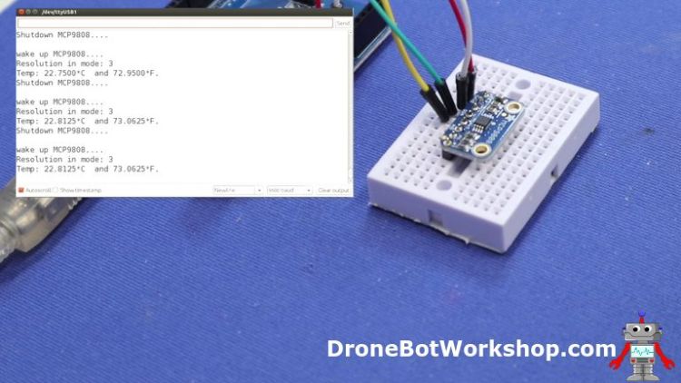
Load the sketch up to the Arduino, open the serial monitor and observe the readings. They are very precise. Once again I gave mine the “finger test” to watch the reading increase in response to my body heat.
If your design calls for high precision temperature measurement then you really can’t go wrong choosing the MCP9808.
Conclusion
You’ll notice that most of our demo code displayed the temperature in Celsius. If you would prefer Fahrenheit you can just convert the result mathematically:
(degreesC x 1.8) + 32 = degreesF
As we have seen there are a variety of temperature sensors available for the Arduino and other microcontrollers and microcomputers. They vary in interface type, temperature range, voltage requirements, and accuracy.
No matter what your application you’re sure to find one that will do the job quickly and inexpensively.
Pretty hot stuff if you ask me!
Parts List
Here are some components that you might need to complete the experiments in this article. Please note that some of these links may be affiliate links, and the DroneBot Workshop may receive a commission on your purchases. This does not increase the cost to you and is a method of supporting this ad-free website.
COMING SOON!
Resources
Code for this article – In a handy ZIP File.
PDF Article – A PDF version of this article, suitable for printing and using in your workshop.


Thank you so much for making such a detailed and high quality tutorial about temperature sensors.
Very pleased to receive this newsletter. I’m also excited to read about your new Q&A, nicely done sir. I’m a fan of your work and always learn new things from your YouTube channel & website. As a retired Apple bench tech I appreciate all the effort you put into each of your projects. Thank you for sharing your knowledge and experience. Hope you have a early spring, from my location in Vancouver winter is still hanging around.
Until next time, be safe.
Cheers
Dale Marcell
How can I download a PDF of this tutorial?
Where is the code for lm35 I need it okese
Hi need help with my code for my first half of my project and the second half is to add a door lock system with those magnetic cards and key ring all in one and since i started the sketch and saved it for others to help but i am also using liquidecrystal display 16×2 without i2c so if anyone can help let me know. thanks
Thanks for all of the videos! In this video (Measure Temperature with Arduino) you show how to use the external AREF by connecting it to the 3.3V power pin. Supposedly internal reference voltages exist to get even more accuracy (1.1V and 2.56V, depending on the chip). Could you post how this is done for both the ATMega328 (Arduino Uno chip) and for the ATTINY85 chip using Arduino ISP? I’m using an ATTINY85 to measure temperature with a TMP37. The temp will never exceed 100C so I want to use the 1.1V internal reference but I’m having trouble getting the chip… Read more »
Thank you for the tutorials on arduino, Please is it possible to come up with video on fully automatic egg incubator preferable Arduino PID
I think some things on this page are broken.
I can see the text
<INSERT DHT_UNIFIED_SENSOR SKETCH>
some places where I would expect the referenced code to be. You might want to look into this.
Bill, There is no link for the PDF file for the temperature sensors article. PDF’s are very useful to have on your home computer. I like to download everything I work on for future reference. Your tutorials are the very best quality. One comment, often a 10K pullup resistor is used from Vcc (pin 1) to Data out (pin 2) on the DHT 22 sensor. Adafruit points out that the Arduino pullup resistors are very weak, 20-50K, They say “DHT22 and AM2302 often have a pullup already inside, but it doesn’t hurt to add another one” . What do you… Read more »
3 sensor DHT22/AM2302 code, .csv output format // Example testing sketch for various DHT humidity/temperature sensors // Written by ladyada, public domain //Modified 3/15/2021 by Richard Franklin for 3 sensors and .csv output format // Just drop the DHT folder that has DHT.h into the main arduino libraries folder if you don’t //want to install adafruit extra libraries, etc. #include “DHT.h” #define DHT1PIN 2 // what digital pin sensor 1 is connected to #define DHT2PIN 4 // what digital pin sensor 2 is connected to #define DHT3PIN 7 // what digital pin sensor 3 is connected to // Uncoment whatever type you’re using!… Read more »
Fabulous article! Thank you so much for this wealth of information!
Is it possible to use the MCP9808 temp alarm signal to activate another device? Possibly on the same board?Newbee so Thanks!
Great article and video tutorial to accompany it. Thanks so much for sharing. It really helped me solve a problem I run into while trying to use the DHT11 and DHT22 sensors with the Arduino MKR wifi 1010 board.
Keep up the good work Bill.