Table of Contents


Introduction
Liquid Crystal displays or LCDs have been used in electronics equipment since the late 1970s. LCD displays have the advantage of consuming very little current And they are ideal for your Arduino projects.
In this article and in the accompanying video I’ll show you how easy it is to add an LCD display to your next Arduino design. I’ll also show you a very popular Arduino Shield that has a keypad which you can use in your projects as well.
So let’s get started!
LCD Displays
Today LCD displays are used in a variety of items from test equipment to televisions. They’re inexpensive and versatile, this makes them ideal for all sorts of designs.

LCD displays do not emit light. Instead they block the passage of light, like little windows which open and shut the let light through. The liquid crystals used inside LCD displays are sandwiched between two layers of polarized material. By changing the orientation of the liquid crystals they allow light to pass or they block the light entirely.
Because transmissive LCD displays (the type we will be using) work by blocking light they require a backlight. Several methods have been used to create back lights including electroluminescent panels and fluorescent tubes. these days the most common form of backlight is an LED, in fact so-called LED televisions are usually just LCD screens with an LED backlight system.
Another type of LCD display, the passive-matrix display, does not require a backlight, it works using reflected light. This type of display is often found in digital watches.
The low cost and versatility of LCD displays makes them suitable for a number of different applications.
History of Liquid Crystal Displays
The principles of liquid crystals were discovered in the late 1880s but work on Modern LCD displays did not begin until the mid-1960s. a number of patents were filed in the early 1970s and in 1973 the Sharp Corporation introduced LCD displays for calculators.
The first color LCD displays were developed in the early 1980s but production units were not commonly available until the mid-1990s. By the late 1990s LCD displays were quite common.
LCD televisions have been available since the beginning of the 21st century and by 2007 the image quality of LCD surpass that of CRTs.
LCD Displays for Experimenters
A number of LCD displays are available for experimenters. These low-cost monochrome displays are ideal for use with microcontrollers like the Arduino and micro computers like the Raspberry Pi.
These displays are available in a number of different configurations. The part number for the display generally relates to the number of rows and columns in the display.
Common display configurations include 16 x 2, 16 x 4 and 20 x 4. All of these displays are used in a virtually identical fashion the only difference being the number of columns and rows they have.
We will be using a 16 x 2 display in our experiments but you could substitute another configuration with some minor code changes.
LCD1602 Display Module
The LCD1602 display module is a very popular and inexpensive LCD display. It is available in a number of different colors such as blue yellow and green and can easily be connected to an Arduino or Raspberry Pi.
The display consists of two rows of 16 characters each. It interfaces through a parallel data interface and has an LED backlight.
In operation data is sent down the parallel data lines for the display. There are two types of data that can be sent to the display. The first type of data are the ASCII characters which are to be displayed on the display. The other type of data are the control characters that are used to activate the various display functions.
LCD1602 Pinouts
The LCD1602 display has 16 solder pads that you can use in a number of ways:
- You can solder a connector directly to it. Typically a 16-pin male header is soldered here with the pins facing the back of the circuit board.
- You could solder wires directly to it, although this isn’t really recommended.
- You can attach an I2C adapter directly to it or you can use a female header strip to allow you to plug in the I2C adapter. More on this later.
The pinout of the connector is as follows:

Here is a breakdown of the pin functions:
- GND – This is the Ground pin. On some modules it is labeled VSS.
- 5 VDC – This is the 5 volt power connection. On some modules it is labeled VDD.
- Brightness – This is the input for the brightness control voltage, which varies between 0 and 5 volts to control the display brightness. On some modules this pin is labeled V0.
- RS – This is the Register Select pin. It controls whether the input data is meant to be displayed on the LCD or used as control characters.
- RW – Puts the LCD in either Read or Write mode. In most cases you’ll be using Read mode so this pin can be tied permanently to ground.
- EN – The Enable pin. When High it reads the data applied to the data pins. When low it executes the commands or displays the data.
- D0 – Data input 0.
- D1 – Data input 1.
- D2 – Data input 2.
- D3 – Data input 3.
- D4 – Data input 4.
- D5 – Data input 5.
- D6 – Data input 6.
- D7 – Data input 7.
- A – The Anode (positive voltage) connection to the backlight LED.
- K – The Cathode (ground or negative voltage) connection to the backlight LCD.
4-Wire Mode
Because the LCD module uses a parallel data input it requires 8 connections to the host microcontroller for the data alone. Add that to the other control pins and it consumes a lot of connections. On an Arduino Uno half of the I/O pins would be taken up by the display, which can be problematic if you want to use the I/O pins for other input or output devices.
One way of reducing the number of connections required is to use 4-wire mode, and most projects that make use of this display do exactly that.
In 4-wire mode the data is sent a half a byte at a time, thus requiring only 4 data connections. The upper half of the data input (D4 to D7) is used while the other pins are not connected to anything.
All of the experiments that use direct connection to the LCD module will use 4-wire mode.
Another method of reducing the number of connections to the display is to use the I2C adapter. We will discuss this further later in this article.
Arduino Sketches with LCD1602
We will begin our experiments by hooking up the LCD1602 to an Arduino Uno and running a few of the example sketches included with the Arduino IDE. This will allow you to get familiar with the display without needing to write any code.
Hooking up the LCD1602 to Arduino
We need to hookup our LCD display to our Arduino. The display can use any of the Arduino digital I/O pins as it has no special requirements, but if you hook it up as I’ve illustrated here you can run the example sketches without needing to make any modifications.

In addition to the LCD1602 display ands the Arduino Uno you will need a 10K trimpot ot potentiometer, this is used a s a brightness control for the display. You’ll also need a 220 ohm resistor to drop the voltage for the displays LED backlight.
After you get your parts hooked up you’ll be ready to run the sketches.
Arduino Example Sketches
The Arduino IDE includes the LiquidCrystal library and this library has a number of example sketches. I’ll go over three of them here but you can also try the other ones.
You can use these example sketches as a basis for developing your own code for the LCD display module.
To access the example sketches perform the following steps:
- Open the Arduino IDE.
- Click on the File menu at the top of the IDE,
- Click on Examples. A sub-menu will open.
- Scroll down the sub-menu to the Examples from Custom Libraries section.
- Select LiquidCrystal.
- You will see a selection of example sketches. Select any of them to load the sketch into your IDE.
Let’s begin with the classic beginning, Hello World.
Hello World Sketch
Load the HelloWorld sketch from the example sketches into your Arduino IDE.
The sketch starts with a number of credits and a description of the required hardware hookup. You’ll note that this is the same hookup you just performed on your Arduino and LCD module.
In the beginning of the actual code we load the LiquidCrystal library.
We then initialize an object that we call “lcd” using the pinouts of the LCD display. If you decide to hook up your display to different pins then you’ll need to modify this section.
In the setup routine we initialize the LCD for 16 x 2, if you are using a different LCD module you would change this accordingly.
We also write “hello, world!” to our LCD in the setup. As we did not specify the cursor location this will print at the beginning of the first row.
Now onto the loop.
In the beginning of the loop we set our cursor to the first position in the second row. Note that the row numbers start with zero so the second row is row 1.
We then use the millis function to print out every second (1000 milliseconds) on the display.
That ends the loop, so we start back at the top of the loop and repeat. The result will be a counter on the second line that counts seconds from the htime the Arduino was last reset.
Load the sketch up to your Arduino and observe your display. If you don’t see anything try adjusting the brightness control that you wired to the display.
Now let’s move on to another sketch.
Scroll Sketch
The second example we will try is the Scroll sketch. Scrolling is a useful technique when you can’t get your text to fit on one line of the LCD display.
Look in the LiquidCrystal examples menu for Scroll and load it into your Arduino IDE.
Scroll begins in an identical fashion to the Hello World sketch, including loading the text “hello, world!” on the display in the setup routine.
The loop is where the action is!
In the loop the code demonstrates the use of the scrollDisplayLeft and scrollDisplayRight functions. As their names imply they move the text in a left or right direction.
In each case the functions are encased in a for-next counter, for each increment the text is scrolled one position in the appropriate direction.
There are three such counters. The first one scrolls the text left by 13 positions, which is enough to move it off the display to the left.
The second counter moves the text 29 positions to the right, which will bring it back onto the display and then move it off to the right.
Finally the last counter moves the text 16 positions to the left again, which will restore it back to the center of the display. The loop then repeats itself.
Custom Characters
One final sketch to look at is the Custom Character sketch, as it illustrates an important concept.
Custom characters are useful when you want to display a character that is not part of the standard 127-character ASCII character set. Thi scan be useful for creating custom displays for your project.
A character on the display is formed in a 5 x 8 matrix of blocks so you need to define your custom character within that matrix. To define the character you’ll use the createChar function of the LiquidCrystal library. You are limited to defining a maximum of eight characters.
To use createChar you first set up an array of bytes with 8 elements. Each element in the array defines one row of the character in the 5 x 8 matrix. You then use createChar to assign a number from 0 to 7 to that array.
Custom Character Arduino & LCD Hookup
The Custom Character demonstration requires one additional component to be wired to the Arduino, a potentiometer (10K or greater) wired up to deliver a variable voltage to analog input pin A0.
The extra wiring is illustrated here:

Once you have that wired up you can proceed to load the sketch, examine it and then try it out.
Custom Character Sketch
Load the CustomCharacter example sketch in to your Arduino IDE and examine the code.
As with the previous sketches we examined this one starts by loading the LiquidCrystal library and defining an object called lcd with the connection information for the display. It then moves on to define the custom characters.
Each character is defined as an array with 8 elements, the zeros and ones in the array indicate which elements in the character should be on and which ones should be off. Five arrays are defined, although the sketch actually only used four of them.
The last two arrays, amsUp and armsDown define the shape of a little “stickman”, or “stickperson” if you want to be politically correct! This is done to show how we can animate a character on the display.
The setup begins by defining the size of the LCD display, just as the previous sketches did.
Then the five custom characters are assigned a unique integer using the createChar function. Remember, you can define a maximum of eight custom characters in a sketch.
Finally the setup routine ends by printing a line to the first row of the LCD display. The line makes use of two of the custom characters, the “heart” and the “smiley”.
Note that custom character “0” is a special case as it must be cast specifically as a byte. This is optional for the other custom characters.
Now we move onto the loop.
We begin by reading the value of the voltage on pin A0 using the Arduino analogRead function. As the Arduino has a 10-bit analog to digital converter this will result in a reading ranging from 0 to 1023.
We then use an Arduino map function to convert this reading into a range from 200 to 1000. This value is then assigned to an integer called delayTime, which as its name implies represents a time delay period.
Now it’s time to animate our stick figure.
First we set the cursor to the fifth position on the second row. We then draw our character with his (or her?) arms down.
Next we delay by the amount of time specified by the delayTime variable. Remember this value is determined by the position of the potentiometer.
We then draw the character with arms up. And we repeat the same delay.
This is the end of the loop so we go back to the top and do it all again.
The end result is that our character wil wave his arms up and down at a speed determined by the position of the potentiometer.
Load the sketch and give it a run. Experiment with turning the controls and watch the little stick person in action!
Using I2C Adapter
One thing you may have noticed about using the LCD display module with the Arduino is that it consumes a lot of connections. Even in 4-wire mode there are still a total of seven connections made to the Arduino digital I/O pins. As an Arduino Uno has only 14 digital I/O pins that’s half of them used up for the display.
In some cases that’s fine as your project may only need a couple of other pins or it might rely exclusively on the analog pins. But still that’s a lot of wiring.
In other cases you would need to resort to using some of the analog pins as digital pins or even moving up to an Arduino Mega which has many more I/O pins.
But there is another solution. Use the I2C bus adapter for the LCD display and connect using I2C. This only consumes two I/O pins and they aren’t even part of the set of digital I/O pins.
The I2C Bus
The I2C or IIC bus is the Inter Integrated Circuit bus. It was developed by Philips Semiconductors in 1982 for use in the television industry. The idea was to allow the integrated circuits in televisions to “talk” to one another using a standard bus.
The bus has evolved to be used as an ideal method of communicating between microcontrollers, integrated circuits, sensors and micro computers. You can use it to allow multiple Arduinos to talk to each other, to interface numerous sensors and output devices or to facilitate communications between a Raspberry Pi and one or more Arduinos.
The bus only uses four connections, two of them are for power:
- Power – This can be either 5 Volts or 3.3 volts, depending upon the application. Note that there are many precautions that must be observed if you are interfacing a 3.3 volt and 5 volt I2C device on the same bus.
- Ground – The ground connection.
- SDA – Serial Data. This line is used for both transmit and receive.
- SCL – Serial Clock. This is a timing signal supplied by the Bus Master device.
In I2C communications there is the concept of Master and Slave devices. There can be multiples of each but there can only be one Master at any given moment. In most Arduino applications one Arduino is designated Master permanently while the other Arduinos and peripherals are the Slaves.
The Master transmits the clock signal which determines how fast the data on the bus is transferred. There are several clock speeds used with the I2C bus. The original design used 100 KHz and 400 KHz clocks. Faster rates of 3.4 MHz and higher are available on some I2C configurations.
For most Arduino designs a 400 KHz clock frequency is used.
Every device on the I2C bus has a unique address. When the Master wants to communicate with a Slave device it calls the Slaves address to initiate communications.
In our simple design we will be using our Arduino as a Master and the I2C adapter for the LCD display as the Slave.
I2C Adapter
The I2C Adapter for the LCD display is a tiny circuit board with 16 male header pins soldered to it. These pins are meant to be connected directly to the 16-pin connection on the LCD1602 display (or onto other displays that use the same connection scheme).
The device also has a 4-pin connector for connection to the I2C bus. In addition there is a small trimpot on the board, this is the LCD display brightness control.
Most of these devices have three jumpers or solder pads to set the I2C address. This may need to be changed if you are using multiple devices on the same I2C bus or if the device conflicts with another I2C device.
Hooking up the Arduino to I2C
The Arduino Uno uses two of the analog input pins as its I2C connection. A4 is used as the SDA connection while A5 is used as the SCL connection.
Most Arduino Unos also have some dedicated pins for I2C, these are internally connected to A4 and A5 and are usually located above the 14 digital I/O pins. Some models of the Uno have additional I2C connectors as well.
The following diagram illustrates how to hook up an Arduino Uno to an LCD display with the I2C bus adapter:
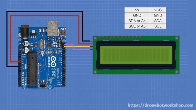
Note how much easier it is to use the I2C connection, which does not consume any of the Arduino Unos 14 digital I/O pins. Since A4 and A5 are being used for the I2C bus they can’t be used as analog inputs in this configuration.
Determining the I2C Address
Not all I2C adapters have the same I2C address, Most have address 0x20 but some use address 0x27 or 0x3F. You can change the address of your adapter by shorting some of the solder pads on the board.
If you don’t know the address you’ll need to find it out before you can run the sketches I’m about to show you. Fortunately there is a simple way of doing this, thanks to the great work of Nick Gammon.
Nick has written a simple I2C scanner sketch that he’s put into the public domain. It scans your I2C bus and gives you back the address of every I2C device it finds. I’ve repeated Nick’s sketch here, it’s also in the ZIP file that you can download with all of the code for this article.
|
1 2 3 4 5 6 7 8 9 10 11 12 13 14 15 16 17 18 19 20 21 22 23 24 25 26 27 28 29 30 31 32 33 34 35 36 37 38 39 40 |
// I2C Scanner // Written by Nick Gammon // Date: 20th April 2011 #include <Wire.h> void setup() { Serial.begin (9600); // Leonardo: wait for serial port to connect while (!Serial) { } Serial.println (); Serial.println ("I2C scanner. Scanning ..."); byte count = 0; Wire.begin(); for (byte i = 8; i < 120; i++) { Wire.beginTransmission (i); if (Wire.endTransmission () == 0) { Serial.print ("Found address: "); Serial.print (i, DEC); Serial.print (" (0x"); Serial.print (i, HEX); Serial.println (")"); count++; delay (1); // maybe unneeded? } // end of good response } // end of for loop Serial.println ("Done."); Serial.print ("Found "); Serial.print (count, DEC); Serial.println (" device(s)."); } // end of setup void loop() {} |
Load this sketch into your Arduino then open your serial monitor. You’ll see the I2C address of your I2C LCD display adapter. You can then make note of this address and use it in the sketches we’ll be looking at now.
Nick also has some great material about using I2C on his blog, you should check it out.
The NewLiquidCrystal Library
In order to run the subsequent sketches you’ll need to install another library. This is the NewLiquidCrystal library which, as its name implies, is an improved version of the LiquidCrystal library packaged with your Arduino IDE.
This library includes libraries for running the I2C adapter, which is why we are going to use it. But ist also can be used as a replacement for the original LiquidCrystal library and it offers improved performance over the original.
You can download the library from the repository on BitBucket. Select the latest version of the library from the list and download the ZIP file.
Once you download the library ZIP file you’ll need to install it in your Arduino IDE. To do this follow these instructions:
- Open the Arduino IDE.
- Click on the Sketch menu at the top of the IDE.
- Choose Include Library from the drop-down menu.
- Select Add .ZIP Library… from the sub-menu.
- A dialog box will open. Navigate to the location you downloaded the ZIP file to and select the file.
- The library will be installed.
Note that since this library uses many of the same functions as the original LiquidCrystal library you may want to remove the original.
I2C Demo Sketch
Now that we have the NewLiquidCrystal library installed we are ready to work with it. First we will run a simple demo sketch to see how it works.
Remember that you’ll need to know the address of your I2C adapter before you run this sketch, so if you don’t know it go back and run Nick Gammon’s I2C Scanner first.
Here is the sketch we will use for our demonstration:
|
1 2 3 4 5 6 7 8 9 10 11 12 13 14 15 16 17 18 19 20 21 22 23 24 25 26 27 28 29 30 31 32 33 34 35 36 37 38 39 40 41 42 43 44 45 46 47 48 49 50 51 52 53 54 55 56 57 58 59 60 61 62 63 64 65 66 67 68 69 70 71 72 73 74 75 76 77 78 79 80 81 82 83 84 85 86 87 88 89 90 91 92 |
/* LCD Display with I2C Interface Demo lcd-i2c-demo.ino Use NewLiquidCrystal Library DroneBot Workshop 2018 https://dronebotworkshop.com */ // Include Wire Library for I2C #include <Wire.h> // Include NewLiquidCrystal Library for I2C #include <LiquidCrystal_I2C.h> // Define LCD pinout const int en = 2, rw = 1, rs = 0, d4 = 4, d5 = 5, d6 = 6, d7 = 7, bl = 3; // Define I2C Address - change if reqiuired const int i2c_addr = 0x3F; LiquidCrystal_I2C lcd(i2c_addr, en, rw, rs, d4, d5, d6, d7, bl, POSITIVE); void setup() { // Set display type as 16 char, 2 rows lcd.begin(16,2); // Print on first row lcd.setCursor(0,0); lcd.print("Hello world!"); // Wait 1 second delay(1000); // Print on second row lcd.setCursor(0,1); lcd.print("How are you?"); // Wait 8 seconds delay(8000); // Clear the display lcd.clear(); } void loop() { // Demo 1 - flash backlight lcd.setCursor(0,0); lcd.print("Backlight demo"); lcd.setCursor(0,1); lcd.print("Flash 4 times"); delay(3000); lcd.clear(); // Flash backlight 4 times for(int i = 0; i< 4; i++) { lcd.backlight(); delay(250); lcd.noBacklight(); delay(250); } // Turn backlight back on lcd.backlight(); // Demo 2 - scroll lcd.setCursor(0,0); lcd.print("Scroll demo - "); delay(1500); // set the display to automatically scroll: lcd.autoscroll(); // print from 0 to 9: for (int thisChar = 0; thisChar < 10; thisChar++) { lcd.print(thisChar); delay(500); } // turn off automatic scrolling lcd.noAutoscroll(); // clear screen lcd.clear(); //Delay delay(1000); } |
The sketch starts by loading the Arduino Wire library. This is the Arduino library that facilitates communications over I2C and it’s part of your Arduino IDE installation.
Next we include our NewLiquidCrystal library for I2C.
On the next line we define the connections to the LCD display module from the I2C Adapter,. Note that these are NOT the connections from the Arduino, they are the connections used by the chip on the adapter itself.
Some adapters use a different set of connections. If you can’t get the sketch to work try the following alternative set of connections;
const int en = 4, rw = 5, rs = 5, d4 = 0, d5 = 1, d6 = 2, d7 = 3, bl = 7;
Before you try this make sure that your problem isn’t that you are using an incorrect I2C address!
Speaking of the I2C address it is defined in the next line and assigned to the variable i2c_addr. Change it to match your I2C address if necessary.
Again we define an I2C object with the connection and I2C address information we just supplied.
In setup we set the size of the display and then print “Hello world!” on the first line in the first position. After a short delay we print “How are you?” on the second line.
We then delay eight seconds, clear the display and end the setup.
In the loop we run a couple of demonstrations to show the use of the library with an I2C device.
The first demo flashes the backlight on and off four times by alternating the use of the backlight and nobacklight functions. When we are done we turn the backlight on again.
The next demo uses the autoscroll function to scroll some text. We first print the text “Scroll demo – “ and then implement a counter to count from 0 to 9 while scrolling the text.
Finally we clear the screen, wait a second and start the loop all over.
Load the sketch and run it on your Arduino. If you can’t get it to work check out the address and connection information to be sure you have it right.
Once you do get it working you’re ready to build something practical with your LCD display and I2C adapter.
Build a Temperature & Humidity Gauge
By now I’m sure you are tired of just displaying text and characters on your display. So we’ll build something practical now.
In this project we will put together a digital temperature and humidity gauge. It’s pretty accurate thanks to the use of a DHT22 temperature and humidity sensor. You could also substitute a cheaper DHT11 sensor but it won’t be as accurate.
Temperature & Humidity Gauge Hookup
We need to make a minor wiring adjustment to the hookup with our I2C adapter, specifically we will need to add a DHT22 temperature and humidity sensor into the circuit. The wiring is shown here:

As you can see the DHT22 is connected with its output tied to pin 7 of the Arduino. The other two connections are 5 volts and ground. Note that pin 3 of the DHT22 is not used.
After you have the wiring done proceed to load the sketch.
Temperature & Humidity Gauge Sketch
The sketch for the temperature and humidity gauge is presented here:
|
1 2 3 4 5 6 7 8 9 10 11 12 13 14 15 16 17 18 19 20 21 22 23 24 25 26 27 28 29 30 31 32 33 34 35 36 37 38 39 40 41 42 43 44 45 46 47 48 49 50 51 52 53 54 55 56 57 58 59 60 61 62 63 64 65 66 67 68 69 70 |
/* LCD Display with I2C Interface and DHT-22 Temp/Humid Sensor lcd-i2c-temp-humid.ino Use NewLiquidCrystal Library Use DHT Libraries from Adafruit DroneBot Workshop 2018 https://dronebotworkshop.com */ // Include Wire Library for I2C #include <Wire.h> // Include NewLiquidCrystal Library for I2C #include <LiquidCrystal_I2C.h> // Include DHT Libraries from Adafruit // Dependant upon Adafruit_Sensors Library #include "DHT.h"; // Define LCD pinout const int en = 2, rw = 1, rs = 0, d4 = 4, d5 = 5, d6 = 6, d7 = 7, bl = 3; // Define I2C Address - change if reqiuired const int i2c_addr = 0x3F; // DHT-22 #define DHTPIN 7 // DHT-22 Output Pin connection #define DHTTYPE DHT22 // DHT Type is DHT 22 (AM2302) // Define LCD display connections LiquidCrystal_I2C lcd(i2c_addr, en, rw, rs, d4, d5, d6, d7, bl, POSITIVE); // Define Variables float hum; // Stores humidity value in percent float temp; // Stores temperature value in Celcius // Setup DHT sensor for normal 16mhz Arduino DHT dht(DHTPIN, DHTTYPE); void setup() { // Set display type as 16 char, 2 rows lcd.begin(16,2); // Initialize DHT-22 dht.begin(); } void loop() { delay(2000); // Delay so DHT-22 sensor can stabalize hum = dht.readHumidity(); // Get Humidity value temp= dht.readTemperature(); // Get Temperature value // Clear the display lcd.clear(); // Print temperature on top line lcd.setCursor(0,0); lcd.print("Temp: "); lcd.print(temp); lcd.print(" C"); // Print humidity on bottom line lcd.setCursor(0,1); lcd.print("Humid: "); lcd.print(hum); lcd.print(" %"); } |
Keep in mind that you may need to modify it for the address and connections used by your I2C Adapter, just like in the previous sketch.
This sketch also makes use of the DHT library from Adafruit. We used this library in a previous article, “Using the HC-SR04 Ultrasonic Distance Sensor with Arduino” so you may want to take a look at that one in order to get it installed.
The key thing to note is that this library is dependant upon another Adafruit library, their Unified Sensor library. Both can be installed using the Library Manager in your Arduino IDE.
The sketch is similar to our demo sketch in that it creates an “lcd” object with the I2C and display connection information. It also defines a couple of parameters for the DHT22 sensor, as well as some floating variables to hold the temperature and humidity values.
In the setup we set the display as a 16 x 2 display and initialized the DHT22 temperature and humidity sensor.
We start the loop with a two second delay, this is necessary as the DHT22 sensor needs to stabilize before taking a reading.
After the waiting period we take the temperature and humidity readings from the DHT22 and assign them to their respective variables.
We then print these values to the LCD display. And that’s it, the loop repeats and updates the display every two seconds. It’s as simple as that!
Load the sketch to your Arduino and observe the display. You should now have an accurate temperature and humidity gauge.
Note that this displays the temperature in Celsius. If you want to change this to Fahrenheit its a simple matter of using some math. The formula ( temp * 1.8 ) + 32 will convert the results to Fahrenheit.
Arduino LCD Keypad Shield
So far we have used the LCD1602 display module for all of our experiments. For our final demonstration we’ll switch to a popular Arduino shield that contains a LCD1602 along with some push buttons.

The LCD Keypad Shield is available from several different manufacturers. The device fits onto an Arduino Uno or an Arduino Mega and simplifies adding an LCD display to your project.
LCD Keypad Shield Push Button Operation
The LCD Keypad Shield has 6 push buttons, labeled as follows:
- Right
- Left
- Up
- Down
- Select
- Reset
The Reset button is simply connected to the Arduino Reset pin and works just like the Reset button on the Arduino itself. This is common on many shields as the shields physically cover the Reset button.
The other five push buttons can really be used for anything you’d like to use them for. And the way they are hooked up is very interesting, at least it is to me!
At first glance you might expect that the push buttons simply connect to some of the Arduino digital I/O pins. But that’s not how they work.
Instead the buttons are connected to a resistor array that acts as a voltage divider. The entire array is connected to the Arduino’s analog A0 pin. One pin for five push buttons.
Here is the button arrangement:

Pressing each button will send a voltage to the analog A0 pin. Because of the arrangement of the resistors each button will send a different voltage to the analog pin. By measuring the voltage level you can determine which button was pressed.
Simple yet ingenious!
Using the Arduino analogRead function on pin A0 the following readings are obtained for each push button:
- Right – 0
- Up – 144
- Down – 329
- Left – 504
- Right – 741
We can use these values to determine which button has been pressed. We will do that in our demo sketch in a moment.
LCD Keypad Shield Connections
Internally the LCD Keypad has the following connections:

Note that the LCD is being used in 4-wire mode. The LCD itself is the same one used on the LCD1602 module, so all of the code for that module will work with the LCD Keypad Shield as well.
Now that you know how the LCD Keypad module works and which Arduino pins it uses all that remains is to install it onto your Arduino and load the demo sketch.
One thing – once the shield is installed on the Arduino you won’t have easy access to the unused I/O pins to connect any sensors or output devices you may want to use (although the demo sketch doesn’t need anything else connected). There are a couple of ways to get around this:
- Solder some pins to the solder pads on the LCD Keypad display, this is exactly what they are for.
- Use a shield that exposes the pins for prototyping before you install the LCD Keypad shield. In the video associated with this article I use a “Screw Shield” that brings all of the Arduino I/O pins out to a series of screw connectors. There are other similar shields. Using one of these shields is the easiest way to work with the LCD Keypad shield, as well as other Arduino shields.
Now let’s look at the demo sketch.
LCD Keypad Shield Demo Sketch
The demo sketch is very simple, all it does is detect which push button you press and display it on the LCD display. Here’s what it looks like:
|
1 2 3 4 5 6 7 8 9 10 11 12 13 14 15 16 17 18 19 20 21 22 23 24 25 26 27 28 29 30 31 32 33 34 35 36 37 38 39 40 41 42 43 44 45 46 47 48 49 50 51 52 53 54 55 56 57 58 59 60 61 62 63 64 65 66 67 68 69 70 71 72 73 74 75 76 77 78 79 80 81 82 83 84 85 86 87 88 89 90 91 92 93 94 95 96 97 98 99 100 101 102 103 104 105 106 |
/* LCD Display Shield with Buttons Demo lcd-button-demo.ino Use Display Shield with Analog Buttons DroneBot Workshop 2018 https://dronebotworkshop.com */ // Include LiquidCrystal library #include <LiquidCrystal.h> // Setup lcd object with display pinouts LiquidCrystal lcd(8, 9, 4, 5, 6, 7); // Define button constants #define btnRIGHT 0 #define btnUP 1 #define btnDOWN 2 #define btnLEFT 3 #define btnSELECT 4 #define btnNONE 5 // Define variable to hold current button constant value int lcd_key = 0; // Define variable to hold button analog value int adc_key_in = 0; // Function to read the buttons // Returns button constant value int read_LCD_buttons() { // read the value from the sensor adc_key_in = analogRead(0); // Approx button values are 0, 144, 329, 504, 741 // Add approx 50 to those values and check to see if we are close if (adc_key_in > 1000) return btnNONE; // No button is pressed if (adc_key_in < 50) return btnRIGHT; // Right pressed if (adc_key_in < 195) return btnUP; // Up presed if (adc_key_in < 380) return btnDOWN; // Down pressed if (adc_key_in < 555) return btnLEFT; // Left pressed if (adc_key_in < 790) return btnSELECT; // Select pressed return btnNONE; // If no valid response return No button pressed } void setup() { // Setup the LCD display lcd.begin(16, 2); // Set cursor to top line first position lcd.setCursor(0,0); // Print message on first line lcd.print("Push a button"); } void loop() { // Move cursor to second line, 9 spaces over lcd.setCursor(9,1); // Display seconds elapsed since reset lcd.print(millis()/1000); // Move to the begining of the second line lcd.setCursor(0,1); // Call the read buttons function lcd_key = read_LCD_buttons(); // Print button value on second line switch (lcd_key) { case btnRIGHT: { lcd.print("RIGHT "); break; } case btnLEFT: { lcd.print("LEFT "); break; } case btnUP: { lcd.print("UP "); break; } case btnDOWN: { lcd.print("DOWN "); break; } case btnSELECT: { lcd.print("SELECT"); break; } case btnNONE: { lcd.print("NONE "); break; } } } |
The sketch begins by including the LiquidCrystal library. You can use the original one or the one includes with the NewLiquidCrystal library. We then set up an object with the LCD connections, note that these are just hard-coded as they won’t change.
Next we define a number of constants, one for each of the push buttons. Note that nothing is defined for the Reset button as it simply mimics the Arduino Reset button, however a constant is defined for the “none” condition.
We then define two variables. The first one holds the value of the selected pushbutton, the second holds the analog reading from port A0 where the push button input is detected.
After that we define a function called read_LCD_buttons() . This function reads the value on analog port A0 and returns an integer corresponding to the button integers we defined earlier. Note that the function adds approximately 50 to each of the manufacturers specified values to account for intolerances in the resistors in the voltage divider.
In the setup we simply define the display size and print a message on the first line.
We start the loop by placing the cursor 9 spaces over on the second line. We then use the millis function to display a counter that counts the time since the Arduino was reset. This is to test the Reset button.
We then call our read_LCD_buttons() function and use it to display the value of the push button, right before the counter. Then we end the loop and do it again.
Load the code onto the Arduino and run it. You should see the value of each button as you press it, along with a counter that increments each second. If you press Reset the counter should reset itself back to zero.
It’s a simple demo but you can use the code to build projects using the LCD Keypad Display.
Conclusion
As you can see LCD displays are pretty simple to use thanks to the availability of some excellent libraries for the Arduino. As these displays are also very inexpensive they will make an ideal addition to many of your Arduino projects.
With I2C you can hook up an LCD display without using up all of the precious digital I/O ports on your Arduino.
And finally the LCD Keypad Shield is a convenient method of adding both a display and a simple keypad to your project, no wiring or soldering required.
If you have any questions regarding the use of LCD displays please let me know in the comments below.
Now go and put yourself on display!
Parts List
Here are some components that you might need to complete the experiments in this article. Please note that some of these links may be affiliate links, and the DroneBot Workshop may receive a commission on your purchases. This does not increase the cost to you and is a method of supporting this ad-free website.
COMING SOON!
Resources
Code For This Article – The sketches used in this article, in an easy to use ZIP file.
NewLiquidCrystal Library – The NewLiquidCrystal library that you will need to use the I2C sketches.
Nick Gammons I2C Articles – A great resource for learning about I2C
Sparkfun I2C – Another excellent I2C resource.
Custom Character Generator – Mike Yancey’s cool custom character generator. It even writes the code for you!


Hi Sir, can you plz help me understand how to print bigger numeric font using both lines, for example showing volume level of audio
go to website
Also Sir, I want to learn how to control volume of i2c chip PT 2258 with arduino
Firstly I want to appreciate all your video making, its complete and its very easy to follow. Please do more lot’s. Thank you.
Hi ,
Used your excellent guide to experiment and understand the LCD on I2C.
However – my display dont show any text – backlight and flashing comes as the script says but no
text – is my display faulty or is it just me that have not understood …
Using this display
https://www.kjell.com/se/sortiment/el-verktyg/elektronik/optokomponenter/led-lcd-displayer/luxorparts-lcd-display-2×16-seriell-i2c-p90786#ProductDetailedInformation
Hi,
Just read your post – turn the potentiometer on the backside left or right to change the contrast, till you see the digits.
I tried it but still i have the same problem.
Even i used the external potentiometer and i was able to change the contrast but could not see the letters/digits.
i also have the same problem.
How do you debounce the buttons?
I want to increment a number (i.e increase an integer value by 1) with the press of a button but the return value is gives me a non-linear increase (i.e integer value goes up by 10,20,39 and keeps on increasing as i hold the button down).
Very nice work! I love all your articles and videos. They explain everything in a simple way.
Keep up the good work and thank you!
Hi, Sir…
In the code I2C Demo Sketch, 2 lines were missing …
……………………………………………………………………….
void steup () {
lcd.init (); // initialize the lcd
lcd.backlight (); // turn on backlight
// Set display type as 16 char, 2 rows
lcd.begin(16,2);
……………………………………………………………………….
… for the LCD to initialize.
Your site is very good! I’m learning a lot here.
Thank you for sharing knowledge.
Greetings !
Márcia (Brazil)
Thanks Marcia. That is what I needed to get the demo to work. Also added lines from Aaron’s comments.
Dear Bill, (and all you out there who could help me!) I just bought an MKR zero for an project and tried to play sound with it. For some reason it didn’t worked… Maybe you could make a Video about it??? But now to the LCD. I also couldn’t communicate with a I2C Display: I hooked it up to the SDA and SCL port and used your sketch, but it wouldn’t find the i2c adapter. (Or anything…) I used the Sketch which would recognise the adapter but it didn’t found anything. I tried the same sketch with a Mega and… Read more »
i have never come across such a good site. every topic is explained in a very simple way.
please keep it up.
I’m getting a nan reading.Any idea what might cause this?
sensor is not connected correctly.
Try a different connection. May also be that sensor is not working
Because I suspect you are actually using a DHT11 rather than 22 – less accurate but works if you change to
#define DHTTYPE DHT11 // DHT Type is DHT 22 (AM2302)
I had the same problem. 3pin D11. Turns out the data pin is not the middle pin. It was the left hand pinp, followed by +volts (middle) and -v. Had to find a data sheet to realise the mistake or assumption that I had made about the pins.
For temp. and humidity gauge code, arduino IDE is telling that there is a compiling error. How do I fix it?
for keypad shield code it’s working fine
Thanks so much for your training, very educating and easy to understand.
Hi Bill, Thank you for providing such a marvelous service for us electronic buffs. I have a question dealing with the your lecture on using LCD with Arduino. I have trying to download the new liquid crystal library to my IDE. I downloaded version 1.5.1 to my download page and have attempted to install it to my library manager. I bring up my IDE , click on sketch, choose include library, select add zip file, in dialog box I select location of zip file in downloads and file name is NewLiquidCrystal library 1.5.1. Then I click open. Sometimes a window… Read more »
I have had the same problem. I THINK I found a cure. I removed the Liquid Crystal Library and was able to re-install the NEW liquid crystal library with some success. It is a shame that the new library has the SAME name….
It has cost me many hours of work…
Dave
Thanks for your training and educating, it is easy to understand.
I am a beginner and I will put it into practice.
Sir ,can we read 3 ds19b20 sensors and save it at SD datalogger shield, displaying data in I2C LCD display?
hi sir thank you for the lot of inforation , I want to learn how to control electric compsant with relais
Very helpful to all the beginners like me.. I also subscribed in your Youtube channel.. Thank You
Very informative article – thanks. I am new to this topic and have a problem which you might help with. I have a 4 wire , 4 digit + colon LCD, rescued from some redundant equipment which I would like to reuse but I cannot get it to read from the Arduino. All elements of the display light on connecting power & there is no backlight. Because there are only 4 wires (5V, Com, Data & Clk) I assumed they were I2C but when I run serial monitor it doesn’t detect them. Can you offer any hints on how to… Read more »
Hi, I follow all your vids and have learnt a great deal..thanks. In this tutorial i copy and paste your i2c demo sketch and get the following error when uploading:
Arduino: 1.8.12 (Linux), Board: “Arduino Uno”
sketch_may26b:20:64: error: ‘POSITIVE’ was not declared in this scope
LiquidCrystal_I2C lcd(i2c_addr, en, rw, rs, d4, d5, d6, d7, bl,POSITIVE);
^~~~~~~~
exit status 1
‘POSITIVE’ was not declared in this scope
I scanned i2c address and it is correct. i have tried both sets of connectors with same result. Any ideas?
I just run into the same issue…going to check IC2 Library versions, maybe there is a difference.
I got the code to work- don’t use those lines that gave you an error…type
:
/#include <Wire.h>
#include <LiquidCrystal_I2C.h>
LiquidCrystal_I2C lcd(0x27, 16, 2); // Set the LCD address to 0x27 for a 16 chars and 2 line display
Another Thank you! finally my i2C LCD display worked with your sketch.
Hi. Been a programmer for almost 30 years now (lots of languages but mostly C/C++).Due to lock down I thought I would have a look at “the other side” and chose the Arduino to play with, then I stumbled across this site. Clear and concise tutorials delivered an easy to understand fashion although you say math and not maths. I’m British (Scottish), however I will let you off due to the quality of your tutorials 🙂
Loving the Arduino and please keep up with this website, best I’ve come across!
DroneBot workshop is great , I start working with arduino recently use to do alot of plc programming
worked with c++ and Q basic about 10 year back and have a lot of catching up to do, and DroneBot is the place to be.thank you
I am getting ‘POSITIVE’ was not declared in this scope from the sketch
// Define LCD display connections
LiquidCrystal_I2C lcd(i2c_addr, en, rw, rs, d4, d5, d6, d7, bl, POSITIVE);
Can someone shine a light on this please
Hi,
I have experienced the same and though a newbie this is what i discovered. The New and original libraries have compatibility conflicts and to better understand the problem read bperrybapp’s comments on:
https://github.com/arduino/Arduino/issues/4207.
In essence my work round was to delete my original library from C:\Program Files (x86)\Arduino\libraries and add the New Liquid Crystal. While this allowed the above sketches it failed on my original LC dependent sketches. FYI i have since binned the New LC in favour of the old.
Hope this helps.
Dear Bill,
I’m huge fan of your site and videos. It looks all so neatly done.
Bought a 1602with I2C board from aliexpress.com.
Came to this page and worked in 5 minutes.
thanx
Thanks for all your well presented tutorials.
I have tried many sensors using directions found on the DroneBotWorkShop.
In my research, (for future employment opportunities) I find learning about robots and how they work to be most useful. I am sure that the young folks following your channel will have a head start to a better world.
Thanks again.
Please stay safe. Peace.
Would it be possible for you to update the article with a new link to how to find the NewLiquidCrystal library as the provided link (https://bitbucket.org/fmalpartida/new-liquidcrystal/wiki/Home) no longer works (it says the repository was depreciated on Jully 1st)? This would really help as it is difficult to find the right library by googling it as there are multiple libraries for controlling LCD displays with similar names. Thank you and great guides, really useful for a beginner to electronics!
The library is available from https://github.com/fmalpartida/New-LiquidCrystal if you still need it.
I am glad for this opportunity to congratulate and thank you for the work you are doing and all the effort you are putting in.
Yours sincerely,
Dr. Francois Saayman
I tried to download the library from bit bucket per the link. Bit bucket says the repository is closed. Is it on Github? Thanks
Found another LiquidCrystal_I2C lib on GitHub. The class is not exactly the same but works for the examples once you change the lcd class definition. ,
i was following your video and when i go to upload my sketch i get this error “exit status 1
‘POSITIVE’ was not declared in this scope
the error is coming from:
const int en = 2, rw = 1, rs = 0, d4 = 4, d5 = 5, d6 = 6, d7 = 7, bl = 3;
const int i2c_addr = 0x27;
LiquidCrystal_I2C lcd(i2c_addr, en, rw, rs, d4, d5, d6, d7, bl, POSITIVE);
i do not know what to do to fix my problem or what exactly what pr problem is?
The Bitbucket link is broken, I found the same project on GitHub: https://github.com/fmalpartida/New-LiquidCrystal
At first my LCD was just blinking, but no text was displayed. I found that turning the potentiomer (the big blue one) on the back on LCD fixes the problem. I had to turn it all the way clockwise, the display works now. Also pay attention to I2C address, it’s very important – my was 0x27
Sir i have uploaded your code For scanning the I2C module (i am using it for 16×2 display) and when uploaded it to my aurdino board which is connected with the LCD my serial moninter has stucked upto the scanning…. status i have tried many times and also waited it might generate some address bt it was remsined stuck at scanning.. process only
Sir pls help me find solution for this……
Hi .. If You have problem witch library
Download this https://github.com/fmalpartida/New-LiquidCrystal#readme
install as usuall then go to document find folder with libraries and change name from “New-LiquidCrystal-master” to “NewLiquidCrystal” .
First of all my appreciation on all your work. I have learned a lot and improved on previous knowledge thanks to your tutorials. I wanted to give my 2cents about the I2C module. Personally I don’t recommend the NewLiquidCrystal library. It’s very outdated and also the official link from bitbucket is broken. I have also experienced incompatibility issues with some LCD I2C modules. Instead I use the hd44780 library by Bill Perry. It’s a bit more difficult to use, but I found it much more robust and reliable. Also, it can be installed directly from the Arduino Library Manager. Thanks… Read more »
Hello,
First of all, i’m a beginner with arduino. I’m trying to use a LCD display on a arduino uno.
I’ve used the sketch “I2C scanner” to determine the adress of I2C interface of my display.
That went fine. Then i downloaded the necessary library and the I2C demo sketch.
But then when i want to verify and compile the sketch i keep getting the messages “exit status 1” and “POSITIVE was not declared in this scope”
Is there something i’m doing wrong?
Thank you for your answer
i am new to Arduino and have purchased a couple of Mega 2560 boards, can I substitute these cards or do I need to purchase UNO boards, this is not an issue except that I live in a remote location so need to wait for delivery.
I am getting positive is not declared in the scope in my arduino software pls help me
Hi,
The link to the I2C library is now broken as others have said.
I found this Arduino forum post at: https://forum.arduino.cc/index.php?topic=706874.0
There is a new super LCD library mentioned there, but if you want the library for the sketches on this Dronebot article, then use the Web Archive link mentioned in the third post down sent on Sept 28th.
I downloaded NewLiquidCrystal_1.5.1.zip and installed it as described in the article.
I changed the I2C address to 0x27 for my display and the I2C demo sketch in the article compiled and worked first time!
Thanks all.
Hello. I’m doing your LCD I2C Demo project but I run into the problem at line where POSITIVE is stated. Many people have had the same problem:
“POSITIVE not declared in this scope…” and I can’t find anyone with a solution.
I am staring to pull my hair on this…please, please HELP?
Hi,
There is a lot of confusion over the correct library to use with !2C LCDs. I suspect this is causing the problem with that declaration (POSITIVE).
Have you tried the library I mentioned above? (NewLiquidCrystal_1.5.1.zip) The I2C demo sketch compiled with no errors for me with that library.
Good luck!
Thank you.I get a knowlage
I have been working through the LCD I2C setup to test components before connecting to other parts of project, had no end of head banging trying to figure out why the LCD and I2C couldn’t be found when scanned, to cut a long story short the PCF8574 encoder was missing from the board. Many a frustrating hours 🙁 to discover the board was incomplete 🙁
Executive summary: Forget NewLiquidCrystal, and instead install the hd44780 library from the IDE library manager (see the end of this long post for additional details). June of 2021, and I came here to learn, but instead found a lot of confusion. The first thing I noticed was that there’s an obvious typo in Bill’s article. Around 1/3 of the way down the page (following the I2C Demo Sketch), he says … “Some adapters use a different set of connections. If you can’t get the sketch to work try the following alternative set of connections;const int en = 4, rw = 5, rs… Read more »
Thanks for this well written and presented article. I am a “newbie” and following your instruction I achieved success on the first attempt. Your style of instruction is a pleasure to follow.(You have taught an old dog[60 year old} a new trick).
Have you done any videos with dot matrix displays?
Awesome resource just getting started with arduino got a guitar pickup coil winder in mind.3
d printed some strat bobbins ordered parts from
spark
fun there is enough info here to pull it off. Might use xod to generate code,found about it here
i cant get lcd liqdcristl code
Good day,
The link to NewLiquidCrystal Library gives 404 error?
need skech link for 3 LCD1602 Display Module, link in youtube not working.
Hello. Thanks a lot for all these fantastic tutorials. Just want to also mention that most all links to references are outdated.
I also have found many outdated links in your very fine tutorials.
I am also having problems when using the Web Editor as things like the TOOLS option appears to be missing.
When trying the I2C LiquidCrystal examples neither the Web Based nor the offline versions seem to have these libraries included or available in the library manager. Should I look to github or are you considering an update to your videos.
Thank you for all the enjoyment and education you provide.
Alternate Library: https://github.com/blackhack/LCD_I2C
In Arduino Library Manager, search “LCD_I2C”
At time of writing, “LCD_I2C by Blackhack, Version 2.3.0”
In the code I only had to modify the library and instantiation:
#include
LCD_I2C lcd(0x27, 16, 2);
Sorry, formatting error on above post….
Search Library Manager for “LCD_I2C” find the one by “Blackhack” install.
in code:
change library to: LCD_I2C.h
and change instantiation to : LCD_I2C lcd(0x27, 16, 2);