Table of Contents


Today we will be constructing a developers module that simplifies working with the popular ESP32-CAM. It even has a useful portable power supply that can deliver 3.3 and 5-volts!
Even if you don’t need an ESP32-CAM specific developers module you’ll probably get some great ideas for building something perfect for your own application.
Introduction
The ESP32-CAM is an amazing module that features a camera, microSD card, and flash LED combined with an ESP32 microcontroller – all for under 10 US dollars. With it’s built-in Bluetooth and WiFi, along with a wealth of digital and analog I/O ports this module is a winner for remote control and IoT projects.
However working with an ESP32-CAM module can be a bit daunting, as it isn’t as “breadboard-friendly” and many other microcontrollers which we’ve grown accustomed to working with.
So in order to simplify ESP32-CAM development, I’ve put together a simple project, a developers module that makes working with the ESP-32 a lot easier.
Let me explain why I did this, and why you might consider building something similar for yourself.
Why the Developers Module?
I was getting ready to do a number of experiments with the ESP32-CAM in preparation for another video and article when it dawned upon me how awkward it was working with these amazing little creatures.
So I decided to build a more permanent experimenters platform, one that would resolve all of the annoying bits that make working with the ESP32-CAM more difficult than working with, say, an Arduino, or even another ESP32 without the camera.
And thus this project was “born”! It actually “evolved” from being a simple way of breaking out the pins and mounting the external antenna into a complete developers platform with a built-in portable power supply.
ESP32CAM Prototyping Issues
So what are these ESP32-CAM Developers issues that I find so annoying? Actually, there are a few, but the main ones are as follows:
- The Reset switch is on the BOTTOM of the module, meaning you have no access to it on a solderless breadboard. And you need to have access to it.
- Even if you do get it onto a breadboard it eats up a lot of the pins. There is only space left for one connection to each module pin.
- You need to ground the GPIO IO0 pin when programming the module.
- Speaking of programming, you need an external FTDI adapter to program the module, or to use the serial monitor.
- If you don’t have enough current to get the radio started for Bluetooth or WiFi you’ll receive a “Brownout” error message. This is not unique to the “CAM” module, it’s an issue with most ESP32 modules.
- If you add an external antenna it becomes even more awkward to experiment with this module.
Another consideration is that in the “real world” you often need to test your creation in remote areas, away from your workbench or perhaps even away from electricity (i.e. the rafters of your attic). Being tethered to a USB cable and computer doesn’t make that very easy, so a portable power supply would be in order.
Now, to be fair, there are other ways around most of these issues. For example, the ESP32-CAM module can still be used on a solderless breadboard, providing that you place it at the very end and use a toothpick or paperclip to access the Reset switch. Not exactly convenient, but workable. And most folks just bypass the breadboard altogether and just use female jumper wires.
Developers Module Features
The Developers module that I built has the following features:
- Integrated solderless breadboard for simple experiments.
- Integrated power supply with 5-volt and 3.3-volt output. Powered by both battery and AC adapter. The power supply may be used (or built) independently of the developers module.
- FTDI Module connector.
- FTDI Voltage Selector.
- Access to all ESP32-CAM GPIO pins through both male and female connectors, for improved wiring and test-probe flexibility.
- Multiple connector pins for +5-volts, +3.3-volts, and Ground to facilitate wiring experiments.
- Dedicated LED (with dropping resistor) and a pushbutton for experiments.
- The camera is tilted for a better view.
- Access to the ESP32-CAM Reset switch.
- IO0 Jumper for Programming Mode.
- Support for an external antenna.

Building the ESP32-CAM Developers Module
I wired the Developers module and power supply using perfboard and wire-wrap wire (which I soldered, not wire-wrapped). It took me a long afternoon, about 5 hours, to complete the project.
I made use of parts I had around the workshop, and you can do the same, so the parts list is very flexible. And you can design an “improved” version of this module with more LEDs and pushbuttons, or one that supports a different microcontroller.
It’s all up to you how you want to build it, you can create an identical device to the one I built or you could improvise and make something truly unique!
Parts for Module
Here are the parts I used for the module. This list does NOT include the portable power supply, which we will get to in a moment:
- (1) ESP32-CAM Module
- (1) External Antenna & connector (optional)
- (1) FTDI Adapter with 6-pin male header
- (1) Red LED, 3mm
- (1) SPST N/O pushbutton switch, PCB mount
- (1) Resistor, 82 ohm, ¼ w
- (1) 3cm x 7cm perfboard
- (1) 5cm x 7cm perfboard
- (1) Solderless Breadboard, 180-pin
- (2) Female Dupont Header, 16-pin
- (2) Female Dupont Header, 8-pin
- (1) Female Dupont Header, 6-pin
- (1) Female Dupont Header, 4-pin
- (3) Female Dupont Header, 3-pin
- (1) Male Dupont Header, 16-pin
- (1) Male Dupont Header, 16-pin, 90-degree
- (2) Male Dupont Header, 3-pin
- (1) Male Dupont Header, 2-pin
- (1) Screw Terminal, 3-pin, 0.2-inch grid
- (2) Jumper Headers, 0.1-inch
You can use 40-pin Female and Male Dupont headers to make all of the required headers, just use a small set of diagonal cutters to cut them to size. On the female headers, you may have to sacrifice a pin or two to make the cut, and you can trim the ends with a small hobby knife. The male ones cut easily.

Module Hookup
The ESP32-CAM Developers Module is built on two pieces of perfboard, one that holds the ESP32-CAM and optional antenna and the other for the remaining components.
Here are the wiring diagrams for both of the boards, starting with the board that holds the ESP32-CAM.

And here is the other board, the one that has the solderless breadboard and FTDI adapter on it:

Read on for a few hints on wiring all of this up.
Module Assembly – Front Section (with ESP32-CAM)
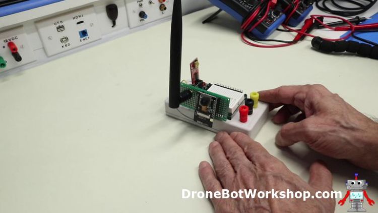
The front assembly, the one that has the ESP32-CAM module and antenna on it, is very easy to wire up. I used a 3cm x 7cm perfboard for this, and before I started wiring the board I drilled a hole to accommodate the antenna connector.
When you are laying out this board DO NOT MAKE THE SAME ERROR I MADE!!
I placed my ESP32-CAM module with the writing right-side-up and the microSD card at the top, as it seemed the most logical way to arrange the board. Turns out that while this arrangement looks great, it actually results in a sideways image!
I will be rewiring another front section board, the beauty of this design is that the modules are interchangeable. When you hook up your front section put the ESP32-CAM module on its side, so that the final image is correctly oriented.

The wiring is very simple for this section, the only challenge is that the two 8-pin female Dupont headers (which hold the ESP32-CAM module) are on the opposite side from the 16-pin female Dupont header that connects this board to the base board.
To make this easier I wired the two 8-pin female headers first, and ran their wires through the perfboard holes right above the 16-pin female header. I did all this without having the 16-pin connector mounted. I then cut and stripped the wires, mounted the 16-pin header on the other side, and soldered each wire.
With all the headers in this project once you get one pin soldered it will hold the header in place, you can “spot solder” each header with a small bit of solder on one pin to hold them while you are assembling the project. Make sure you have them aligned squarely with the pegboard, as once you solder a few pins they can be difficult to adjust.
And teste all your wiring with an ohmmeter after you are done, to make sure all the connections are correct and that there are no short circuits between pins.
Module Assembly – Base Section (with FTDI & Breadboard)
The main board can be wired in sections to make it easier. I suggest not mounting the solderless breadboard until everything is wired and tested with an ohmmeter.

Here is the sequence I used when wiring my board, note that I wired the cross-connections between the front 90-degree header and the two 16-pin headers last.
- Begin by wiring the power section. I used heavier wire for this section, it’s a good idea to do that to allow for a higher current draw. Number 22 or 24 gauge would be a good choice.
- Hook up the 5-volt connection from the 16-pin header to the 5-volt terminal and female headers.
- The 5-volt connection is also run to the 3-pin external power input header and to one side of the 3-pin FTDI Voltage Select jumper.
- You’ll find several Ground connections on the 16-pin ESP32-CAM GPIO bus. I used the one right next to the 5-volt lead to make a ground connection to the center terminal of the screw-terminal block, and to the female Dupont headers used for ground connections.
- Another ground connection is made to the center pin of the 3-pin external power connector.
- We will also connect the ground to the FTDI connector Ground pin, which is on one end of the connector.
- The final power connection from the ESP32-CAM GPIO is the 3.3-volt line, this is connected to the 3.3-volt terminal and female headers.
- We also run the 3.3-volt line to the external power connector.
- And we complete the 3.3-volt wiring by connecting the line to the other end of the FTDI Voltage Select jumper.
- We connect the remaining center pin of the FTDI Voltage Selector jumper to the VCC pin on the FTDI connector. This pin is separated from the Ground pin by the CTS, or Clear To Send pin, which we are not using in our design.
- Now for the FTDI data connections to the ES32-CAM. We start by connecting the UOR, or Receive pin on the ESP32-CAM GPIO to the FTDI adapter TX, or Transmit pin. Remember, the FTDI Transmit goes to the ESP32-CAM Receive, and vice-versa. The FTDI adapter TX pin is right next to the VCC pin we wired in the last step.
- In the same fashion, we connect the ESP32-CAM UOT, or Transmit pin to the FTDI adapter RX, or Receive pin. On both the GPIO and the FTDI adapter these pins are next door to one another.
- Now lets hookup the Poramming jumper, this is the jumper that needs to be closed when you are uploading code to the microcontroller. One side of this 2-pin male header is connected to the ESP32-CAM GPIO pin IO0.
- The other side of the Programming jumper is connected to ground, any ground on the GPIO will work.
- Now we move on to the LED and pushbutton connector, which is a 4-pin female header. Connect the LED+ pin to one side of the 82-ohm resistor, and then connect the other side of the resistor to the LED anode, which is the longer lead.
- Connect the LED- pin to the LED cathode.
- Finally, connect the PB1 and PB2 pins to the two pins of the pushbutton switch, making sure to select the correct two pins. Use an ohmmeter if you are not sure about the pushbutton pinouts, and solder all the pins including the two unused ones, to the board to secure the switch.
- To finish the wiring, connect all 16 connections from the male 90-degree header to the female and male Dupont connectors, pin-for-pin.
Take it a step at a time and test your wiring as you go. If possible, use color-coded wires to make testing and troubleshooting easier.

Once you are done plug the front board into the main board, without the ESP32-CAM module. Use your ohmmeter and test out all 16 connections from the ESP32-CAM sockets to the two connectors at the back of the module. Check out the FTDI and power connections as well.
If all looks good then you can proceed to construct the power supply base.
Building the Power Supply Base
The power supply base would actually make a fine project on its own, if you want to do that then just skip the connection up to the ESP32-CAM Developers module.
One of the first considerations for your power supply will be the enclosure. You’ll want one that can support the ESP32-CAM Developers Module and that can also hold your battery.
I chose a case I happened to have in stock, it was new but was purchased several years ago. It has a length of 12.8 cm, a width of 6.4 cm, and is 2.4 cm tall. That’s 5 inches x 2.5 inches x ⅞ of an inch if Metric is not your thing!
Internally the case had a few plastic standoffs that were already threaded for an M3 screw. I removed most of the standoffs (using diagonal cutters) but retained two of them to mount my circuit board upon.
The ESP32-CAM Developers Module mounts to the top of the enclosure using M2.5 threaded standoffs and nuts, these are the correct size for the mounting holes provided in the perfboard.
The case selection is where you can get creative, so let your imagination do the work. You probably have something around the house that would work just fine, if not then Amazon is a good source of small project cases.
Power Supply Components
You can be very flexible when selecting components for the power supply. Essentially I used a 9-volt battery to drive two small linear regulator modules, a 3.3-volt and a 5-volt one.
All of the parts were chosen on the basis of already being in stroke in my workshop, so feel free to substitute!

Here are the details regarding the parts I used for my power supply base:
- The power supply is based around two linear voltage regulator modules, a 5-volt and a 3.3-volt one. These modules are based around the AMS1117 series of linear regulators and have a very simple pinout. They look identical, so be sure to make a mark on one so you can tell them apart!
- We will need a couple of switches – an SPST switch for power ON-OFF and a DPDT switch for the module power cut-off.
- You’ll also need a power connector for the external power supply. I used a 2.1mm chassis-mount power jack with an internal cutoff switch, which is a very common component. If your intended power supply module uses a different connector you may substitute accordingly, however, note that this design requires a jack with a cutoff.
- We will need a 9-volt battery and a suitable battery snap-on connector. Of course, you can use a different battery if you wish, it will need to be a minimum of 7.5 volts and a maximum of 12-volts for best performance.
- We require three binding posts, preferably color-coded.
- And finally, we’ll need a 3-pin female Dupont jack to connect to the ESP32-CAM developer module.
Once you have your components and case gathered together we can start assembling it.
Power Supply Hookup
Here is the hookup diagram for the power supply base:

Note that the power to the ESP32-CAM Developers Module is supplied via a 3-pin cable with a Dupong female connector.
Also, I didn’t include a power LED with this but it could be easily added if you wish.
Power Supply Assembly
Here is the sequence I used to wire up my power supply:
- Begin the wiring by connecting the negative battery wire to the switch connection on the power jack. Use an ohmmeter with your power jack and test it with a 2.1mm plug if you are unsure of the pinouts.
- Connect the power plug ground connection to the GND connections on the inputs of both voltage regulator modules.
- Now connect the positive battery connection to the positive (tip) connection on the power jack.
- Also, connect the positive power connection to one side of the SPST power switch.
- Connect the other side of the SPST switch to the V IN connections on both regulator modules.
- Connect the V OUT of the 5-volt regulator to the Red binding post.
- Connect the V OUT of the 3.3-volt regulator to the White binding post.
- Connect both regulator output grounds together, and then connect this to the Black binding post.
- Now connect the positive 5-volt output to one outside pole of the DPDT switch.
- Connect the positive 3.3-volt output to the adjacent pole of the switch.
- Finally, we need to hook up the module power cable, the one with a 3-pin female Dupont connector. Start by hooking the 5-volt wire on the outside end to the 5-volt center pole on the DPDT switch.
- Connect the 3.3-volt wire to the other center pole.
- And finish by connecting the ground, or center wire to the output ground.
I built the regulator circuitry on a small scrap of perfboard, with a couple of holes drilled in it to accommodate the two M3 mounting screws I used to hold it in place.

The regulators mount “upside-down” on the board, which is actually a good thing as since the board itself is “upside-down” they end up dissap[ating their heat from the top. I drilled a couple of holes in the perfboard to assist with ventilation, and I also drilled some corresponding holes in the chassis to allow any heat to escape.

I also used another small scrap of perfboard to take advantage of the slots inside my case, many project cases have these for board mounting. I used the small piece of board to hold the wires and the battery in place.
I also used some more right-angled male Dupont headers on the voltage regulator perfboard to connect the external wires. This made for a nice assembly that will come apart easily for troubleshooting. You could, of course, just solder the external connections directly to the perfboard instead.
Testing the Power Supply
After you build the supply you are going to want to test it.
Put a battery in the supply and turn it on. Take a multimeter and measure both the 5-volt and 3.3-volt output. With no load, the outputs should be pretty close to perfect.

Make the same measurements with an external power adapter and no battery. A multimeter at the VIN pins of the regulator will confirm that the battery cutoff is working.

Now turn off the supply and connect the ESP32-CAM Developers module, still without the actual ESP32-CAM module installed.
Turn it back on and verify the operation of the DPDT module power switch, when it is on it should supply 5-volts and 3-3-volts to the module. Measure the voltage at the FTDI connector and on the ESP32-CAM connector to ensure it is correct and wired to the correct pin.

If all of the voltages measure correctly then turn everything off. Mount the developers module onto the power supply. Insert the ESP32-CAM module into its socket, and run the antennal cable.
Testing the Developers Module
You’ll want to give the module a good test to be sure it is all working.
We have already tested the power supply, so we know that is functional. We can use the power supply for our first simple test.
You’ll need three male to male jumper wires to complete these tests, you can use any colors you like of course but you might consider making it a habit of using black for ground and red for power, as that’s fairly standard.
First, connect the 3.3-volts from the 3-pin female Dupont power connector to the LED+ pin. Then connect the Ground 3-pin female Dupont power connector to the LED- pin.

This should, of course, light the LED.
You can then add the pushbutton switch into the circuit by disconnecting the Ground from the LED- and connecting it to one of the switch pins. Connect the remaining switch pin to the LED-.

Now you can control the LED with the pushbutton. As basic as it gets, but it does prove that these simple peripherals are working correctly.
Testing the ESP32-CAM
Testing the camera is best done using the sample sketch that is installed when you set up your Arduino IDE for use with the ESP32.
If you haven’t set up your Arduino IDE yet then you will need to take care of that first. The introductory article Getting Started with ESP32 explains how to do this in detail.
You’ll need to insert an FTDI module into the socket and make sure it is strapped for the same voltage that the ESP32-CAM Developers Module is set to.

You will also need to insert the Programming jumper in order to load a sketch onto the ESP32-CAM. After you finish programming you’ll need to remove it and press the Reset switch on the ESP32-CAM to start the program.
The program we’ll be using is a pretty sophisticated camera test that allows you to stream video, adjust camera settings, and even perform face detection. Load it as follows:
- First, make sure you have selected the correct board using the Boards Manager. The ESP32-CAM board I am using is the popular AIThinker ESP32 CAM.
- Now go into the File menu, select Examples, and scroll down to the Examples for AIThinker ESP32 CAM.
- Select ESP32 and then select Camera from the sub-menu.
- Load the CameraWebServer sketch.
- Modify the sketch for your board definition where it says “Select Camera Model”.
- Provide your 2.4 GHz WiFi SSID and Password.
- Load to the ESP32-CAM. On my module, I need to press the Reset switch when I see the program start to load (after it compiles, which can take some time).
- Remove the Programming jumper from the ESP32-CAM Developers Module.
- Start the Serial Monitor, make sure to set the rate to 115,000 KBps.
- Press the Reset button again to start the program.
Full instructions for running the camera test are in the article Getting Started with the ESP32-CAM.
Resolving “Brownout” Issues
If you run the program while powering the module via the FTDI adapter you may encounter a “brownout” condition. This happens when the ESP32-CAM module starts its radio for WiFi or Bluetooth and tries to draw a large surge of current. Often the computer/FTDI combo is not enough to supply this sudden current draw.

But now you have the solution! The ESP32-CAM Developers Module power supply has plenty of extra current. By using the power from the portable power supply instead of the FTDI adapter you can resolve the “brownout” issue and get an IP address to display your camera on.

And since it is powered by batteries you can move the camera module anywhere within the range of your WiFi and experiment with it.
Conclusion
While I realize that not everyone will want to go to the extent of building a developers module for a specific microcontroller, I think it is worth it for folks who plan on writing a lot of code for the ESP32-CAM. And you can apply the principle to any other microcontroller that you work with often enough to warrant it.
You can also just use it as a portable power supply, it would be very useful for breadboarding logic circuits, and as a general-purpose power supply.
And as long as you didn’t mount the camera module the way I did you’ll also get much better images from your ESP32-CAM.
I’ll be wiring up a new front module right away!
Parts List
Here are some components that you might need to complete the experiments in this article. Please note that some of these links may be affiliate links, and the DroneBot Workshop may receive a commission on your purchases. This does not increase the cost to you and is a method of supporting this ad-free website.
COMING SOON!
Resources


I think you make the best tech videos. I am a mech engr and I always loved electronics and you make it happen for me to participate. Thank you!
Hello Sir, Can you create a video showing how to make this esp32-cam recognize a particular object and then use the output to control a servo motor or a led. Something like a object detection and then reading the output values to control a servo motor.
thanks.
I appreciate your work and the you tube Chanel looking forward to you and Paul Mcworter broadcast tomorrow
I do agree that one need a better way to deal with this modules. I was inspired of your description and I will now try to build my own developers module.
Thank you for your very instructabel video!
Thank You so much for the Tech Video on the ESP32 Cam. Such great info.
Dear Sir, This “ESP32 CAM Developer’s Module” is amazing. Not only the idea of it, but the whole concept: the YouTube video, filmed in your neat and tidy Workshop (I watched the “How I built it”-video and admired it), the way you explain the whole concept, even to the choice of words, the voice etc. English is only my third language, but for your videos I don’t even need subtitles ! I am a certified (?) teacher and your way of teaching technology – sometimes very complicated subjects – is an example for ALL the technology videos on YouTube. I… Read more »
I second that!!! Highly Appreciated!!
I’m a retired Math teacher myself from the U.S. BIll has a excellent balance between telling us enough but yet not too much. My technique is to watch a video and then try experimenting with the content myself. After hopefully some success, I watch the video again. I’ve watched the Intro to ESP32 several times and always seem to understand more each time. Keep up the good work. I have about given up on some of the YouTube videos from folks where English is not their native tongue. I applaud their efforts but often don’t learn much from them.
I have been watching you videos for some time and really enjoy and appreciate your content. I purchased a NUC just prior to seeing your workstation video and had to laugh. I am looking forward to up coming projects. I am trying to create a list of boards and sensors you commonly use, maybe you have created such a list I have not seen yet. Many Thanks
HI, very interesting this project I was planning to do something very similar but adding also audio streaming. I have searched how to add a MIC to the ESP32-CAM and stream the voice along with the image. I could not find anything, maybe it is not possible. Would it be possible?
Can I purchase this developed module??
Can any body help me? I have one esp32 cam espressif. Successfully flash with my FTDI and esp-Tool., but can fix “Brownout” Issues. I use external pover DC-DC 12V to 5V 3A. But not help.
I don’t have an answer for you. I have not experienced Brownout even when using power from the USB to micro cable and my computer. I have been using the bread board power board and a 9V battery when not connected to my computer.
Hi Folks,
Love your tuts and youtube ,very helpfull for beginners like myself 🙂 Do you have any idea what would be the best type of lens to use with the esp32-cam for counting moving objects ,People type objects .Not looking for face recognition or anything fancy just reliable numbers . I’ve seen a couple of different lenses available or maybe a better version of the common $5 esp32-cam module itself..maybe $30 or $40 .
Thanks again ..keep up the great work
Brendan
I found the above to be very interesting. My latest ESP32 CAM came as a kit. This kit included an ESP32 CAM board, a camera which I can’t seem to attach, an external antenna and a programming/power adapter board. This kit included all these items and was very reasonable. It is not a genuine AI Thinker but choosing AI Thinker from the Arduino IDE seems to work. The adapter allows me to connect to my Win 10 computer with a micro connector. This powers the board and also allows me to use my modified Arduino IDE with the ESP32 CAM.… Read more »
Man I could really help you out if I taught you how to use a 3018 cnc to make your own circuit boards and a 3D printer to build those cases. Its really not more time consuming to cnc those boards, I think! But i’m mostly just a frustrated guy and I’m so glad I learned my way out of prototyping hell.