
Table of Contents


Today we are going to take a look at a multitude of air quality sensors, as well as a few temperature and humidity sensors. Let’s see how we can use a microcontroller to monitor the quality of the air we breathe!
Introduction
Air pollution is a growing concern in almost every spot on the planet, including the inside of your home. In addition to the pollutants in the surrounding air, our indoor environments contain several sources of volatile organic chemicals (VOC) and other contaminants.
Monitoring the number of specific gases in the air will allow you to take steps to improve the air quality in your home. Often a strategically placed fan can work wonders.
Today we will look at several sensors designed to measure gas levels and various aspects of air quality. These can be used to construct an air quality monitor, to create an alarm to alert you to specific gas concentrations, or to automatically activate a fan or open a vent when conditions warrant it.

These sensors can work with almost any microcontroller, as well as with many microcomputers. Some of these sensors use the I2C bus to interface with their host, while others use either a serial connection or provide a voltage output for use with an analog-to-digital converter.
Today we will be using these environmental sensors with both an Arduino and an ESP32, but everything we do today applies to just about any microcontroller.
Measuring Air Quality
There are several parameters that you can measure to determine the quality of the air you are breathing.
You can look for levels of specific gases like ozone or carbon dioxide, and the sensors we will be using are available for a wide variety of gases. We will also look at sensors that measure the size of particulate matter, tiny particles of material that are a major cause of pollution and respiratory problems.

We will also measure temperature and humidity. These are not considered to be air quality factors, but accurate temperature and humidity measurements can be used to improve the accuracy of our other sensors. It could also be argued that an environment that is too humid or too dry is also unhealthy.
Noxious Chemicals
Several of these sensors measure the concentration of specific gases. They are made sensitive to these gases with a resistive sensor that is tuned to that specific element, or “elements,” as many of these sensors work with multiple gases.
Some gases that you want to be on the lookout for include:
- Carbon Dioxide – Causes headaches, dizziness, difficulty breathing, and increased heart rate.
- Carbon Monoxide – Reduces blood’s ability to carry oxygen.
- Ozone – Triggers chest pain and throat irritation and can also worsen asthma and bronchitis.
- Nitrogen – Although it’s part of the air we breathe, too much nitrogen can be harmful to the lungs and can worsen common viral infections.
- Sulfur Dioxide – Irritates skin and membranes of eyes, nose, and throat.
Volatile Organic Compounds
Volatile organic compounds, or “VOCs”, are compounds that have a high vapor pressure and low water solubility. Industrial solvents, paints, and refrigerants are primary sources of these chemicals.
VOCs are found in cleaning, disinfecting, cosmetics, degreasing, and other common household products, as well as in paints and varnishes. They can also be emitted by solid objects, including many types of plastics used in office equipment.
Common VOCs include:
- Benzene – Found in tobacco smoke, paint thinner, deodorizers, air fresheners, and furniture polish.
- Formaldehyde – Used in disinfectants, furniture upholstery, carpets, and plywood.
- Ethylene glycol – Included in cleaning agents, personal care products, and perfumes.
- Methylene chloride – Found in spot removers, dry-cleaned clothes, fabric cleaners, and commercial solvents, as well as used in air conditioner refrigerants.
- Tetrachloroethylene – Used in solvents, dry cleaning chemicals, and paint strippers.
- Toluene – Used in paint, metal cleaners, and adhesives.
VOCs can cause many adverse health symptoms, including:
- Eye, nose, and throat irritation.
- Headaches and nausea.
- Loss of coordination.
- Fatigue.
- Dizziness.
- Allergic skin reactions.
Particulate Matter
One of the primary components of pollution is particulate matter, a mix of solid particles and liquid droplets in the air. While some of these particles, like smoke, dust, and soot, are visible to the naked eye, others are so tiny that a microscope would be required to see them.
When measuring Particulate Matter (also called “Particle Pollution”), we reference two standards:
- PM2.5 – Particles with a diameter of 2.5 microns or less.
- PM10 – Particles with a diameter of 10 microns or less.
For reference, the diameter of an average human hair is about 70 microns!
These small particles can enter your lungs and cause respiratory problems.
Air Quality Indicator (AQI)
The Air Quality Index, or AQI, is an attempt to create an easy-to-read standardized indication of the quality of the air.
The following chart shows the levels of the Air Quality Index:

You can calculate the AQI using an online calculator.
MQ Gas Sensors
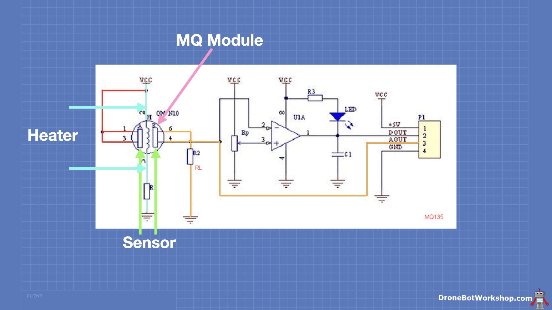
The MQ series of gas sensors are resistive sensors that are usually purchased on a module.
These are resistive sensors known as Chemresistors, and on the module, they are wired in a simple voltage divider circuit so that the module’s voltage output is in proportion to the amount of gas detected.
The modules also have a digital output, which is driven by a comparator. There is a potentiometer on the module that allows you to set a “trip point,” at which the state of the output will go from low to high. You can use this as an interrupt or in a stand-alone configuration for an alarm.
The sensors also have a heater, and on most models, this requires 5 volts to come up to the correct temperature. The modules include a dropping resistor to limit the heater current. These modules can consume quite a bit of current thanks to the heater, so you’ll need to consider that in your design.
There are several different types of MQ sensors; each one is sensitive to specific gases:

The hookup for all of these sensors is identical.
MQ Sensors with Arduino Uno
As the MQ series of gas sensors are designed for 5-volt operation, we will do most of our experimenting with an Arduino Uno.
As you are probably aware, the Arduino Uno has six analog inputs, A0 through A5. These can measure voltages between 0 and 5 volts, which matches the output of the gas sensors when used with a 5-volt power supply.
The Uno also has a 5-volt output, and you can use this to power the MQ gas sensor module, providing that you only intend to power one. If you wish to use multiple modules, you’ll need to provide a power supply. Allow for up to 100ma for each module, as there is a current surge while they are warming up.
Arduino Hookup
Here is how I wired up my MQ gas sensor:

It’s a pretty simple setup, and you can use a different analog port if you wish. Remember that A4 and A5 double as I2C ports, so if you want to use any I2C devices, such as displays or other sensors, you’ll need to avoid those two pins.
MQ Sensor Test Code
A very simple sketch can be used to see if everything is working.
|
1 2 3 4 5 6 7 8 9 10 11 12 13 14 15 16 17 18 19 20 21 22 23 24 25 26 27 28 29 30 31 32 33 34 35 36 37 38 39 40 41 42 43 44 45 46 |
/* MQ Gas Sensor Simple test mq-simple-test.ino Tests operation of MQ-series resistive gas sensors DroneBot Workshop 2022 https://dronebotworkshop.com */ // Define analog input pin for sensor (change as required) #define MQpin (A0) // Variable to store sensor value float sensorValue; void setup() { // Set serial port Serial.begin(115200); delay(1000); // Warm up sensor for 10 seconds Serial.println("Gas sensor requires warm-up period"); for (int i = 10; i >= 1; i--) { Serial.print("Gas sensor warming up, please wait "); Serial.print(i); Serial.println(" seconds."); delay(1000); } } void loop() { // Read sensor pin value sensorValue = analogRead(MQpin); Serial.print("Sensor Value: "); Serial.println(sensorValue); // Delay between readings delay(2000); } |
As I said, it’s pretty simple! We are just reading the level at the A0 analog input on the 10-bit A/D converter and displaying the result on the serial monitor. Nothing to see here, folks!

Actually, there is something to see here! Try exposing the sensor to one of the gases it is sensitive to; I used butane from a lighter with an MQ-2 sensor. Once exposed, the voltage level, and thus the reading on the serial monitor, will increase dramatically.
Arduino MQ Sensor Library
The previous sketch was very simple, but it didn’t give us an accurate reading of the gas compounds. We need to do some math to get that reading, and fortunately, there is a library where all the hard work has been done for you!
The MQSensorsLib library simplifies using MQ gas sensors with Arduino, ESP32, and ESP8266. It works with MQ gas sensors MQ2, MQ3, MQ4, MQ5, MQ6, MQ7, MQ8, MQ9, MQ131, MQ135, MQ136, MQ303A, and MQ309A.
You can install the library directly from the Arduino IDE. Once you have it installed, open up the code examples included with it by navigating to the MQUnifiedSensor menu item in the “Examples from Custom Libraries” section of the example code.
There are dozens of examples included, specific examples for each MQ sensor and some projects like an alcohol meter and a smoke detector.
|
1 2 3 4 5 6 7 8 9 10 11 12 13 14 15 16 17 18 19 20 21 22 23 24 25 26 27 28 29 30 31 32 33 34 35 36 37 38 39 40 41 42 43 44 45 46 47 48 49 50 51 52 53 54 55 56 57 58 59 60 61 62 63 64 65 66 67 68 69 70 71 72 73 74 75 76 77 78 79 80 81 82 83 84 85 86 87 88 89 90 91 92 93 |
/* MQUnifiedsensor Library - reading an MQ2 Demonstrates the use a MQ2 sensor. Library originally added 01 may 2019 by Miguel A Califa, Yersson Carrillo, Ghiordy Contreras, Mario Rodriguez Added example modified 23 May 2019 by Miguel Califa Updated library usage modified 26 March 2020 by Miguel Califa Wiring: https://github.com/miguel5612/MQSensorsLib_Docs/blob/master/static/img/MQ_Arduino.PNG Please make sure arduino A0 pin represents the analog input configured on #define pin This example code is in the public domain. */ //Include the library #include <MQUnifiedsensor.h> /************************Hardware Related Macros************************************/ #define Board ("Arduino UNO") #define Pin (A2) //Analog input 3 of your arduino /***********************Software Related Macros************************************/ #define Type ("MQ-2") //MQ2 #define Voltage_Resolution (5) #define ADC_Bit_Resolution (10) // For arduino UNO/MEGA/NANO #define RatioMQ2CleanAir (9.83) //RS / R0 = 9.83 ppm /*****************************Globals***********************************************/ MQUnifiedsensor MQ2(Board, Voltage_Resolution, ADC_Bit_Resolution, Pin, Type); /*****************************Globals***********************************************/ void setup() { //Init the serial port communication - to debug the library Serial.begin(9600); //Init serial port //Set math model to calculate the PPM concentration and the value of constants MQ2.setRegressionMethod(1); //_PPM = a*ratio^b MQ2.setA(574.25); MQ2.setB(-2.222); // Configure the equation to to calculate LPG concentration /* Exponential regression: Gas | a | b H2 | 987.99 | -2.162 LPG | 574.25 | -2.222 CO | 36974 | -3.109 Alcohol| 3616.1 | -2.675 Propane| 658.71 | -2.168 */ /***************************** MQ Init ********************************************/ //Remarks: Configure the pin of arduino as input. /************************************************************************************/ MQ2.init(); /* //If the RL value is different from 10K please assign your RL value with the following method: MQ2.setRL(10); */ /***************************** MQ CAlibration ********************************************/ // Explanation: // In this routine the sensor will measure the resistance of the sensor supposedly before being pre-heated // and on clean air (Calibration conditions), setting up R0 value. // We recomend executing this routine only on setup in laboratory conditions. // This routine does not need to be executed on each restart, you can load your R0 value from eeprom. // Acknowledgements: https://jayconsystems.com/blog/understanding-a-gas-sensor Serial.print("Calibrating please wait."); float calcR0 = 0; for(int i = 1; i<=10; i ++) { MQ2.update(); // Update data, the arduino will read the voltage from the analog pin calcR0 += MQ2.calibrate(RatioMQ2CleanAir); Serial.print("."); } MQ2.setR0(calcR0/10); Serial.println(" done!."); if(isinf(calcR0)) {Serial.println("Warning: Conection issue, R0 is infinite (Open circuit detected) please check your wiring and supply"); while(1);} if(calcR0 == 0){Serial.println("Warning: Conection issue found, R0 is zero (Analog pin shorts to ground) please check your wiring and supply"); while(1);} /***************************** MQ CAlibration ********************************************/ MQ2.serialDebug(true); } void loop() { MQ2.update(); // Update data, the arduino will read the voltage from the analog pin MQ2.readSensor(); // Sensor will read PPM concentration using the model, a and b values set previously or from the setup MQ2.serialDebug(); // Will print the table on the serial port delay(500); //Sampling frequency } |
In the MQ2 example, we can see how to use the sensor; all the sensors use similar coding. Most of the changes you would need to make are in the definitions, you might need to change the pin number of the A/D converter you’re using, for example.
You’ll also need to edit the Setup section to get the values of setA and setB. These are listed in the code comments, and they differ depending on what gas you are trying to detect.
Most of the “business end” of the code is in the Loop. The sensor is updated and can then be used in your code. The readSensor function will read the value.
Load the code and observe the output on the serial monitor. If you have a sample of the gas you are trying to detect (I used butane with an MQ-2 sensor), then you should be able to see the results change when the sensor is exposed to your sample.
MQ Sensors with ESP32
The ESP32 and other 3.3-volt microcontrollers present a bit of a challenge when using the MQ gas sensors, as most of these sensors require 5 volts for the sensor heater.
If you’re using a “raw” gas sensor, then there is no problem, as you can just wire the heater with 5 volts and use 3.3-volts for the sensor and a dropping resistor.
But if you are using a module, which is the most common way to buy these sensors, then the sensor and its heater are already wired together on the board.
There are three ways to get around this:
1 – Just use 3.3 Volts

The easiest method, simply power the sensor with 3.3-volts. The heater will work, but it won’t reach its full temperature, so the reading will be somewhat inaccurate (although you may be able to recalibrate for the difference). This is certainly the easiest way to use one of these sensors!
2 – Use 5 Volts and a Potentiometer

This method powers the module with 5 volts. The analog output is fed into a potentiometer, allowing you to limit the maximum voltage to 3.3 volts to avoid damaging the ESP32.
This method is a good compromise for accuracy, although “tuning” the potentiometer will take some time. You could replace the potentiometer with a couple of fixed resistors after determining the resistor values.
3 – Modify the Module

For accuracy, this is the best method, but it is also the most complex. It involves modifying the module by cutting traces on its printed circuit board, so if you feel uncomfortable doing this, then this isn’t the best method.
What you need to do is disconnect the side of the resistive element that is currently connected to VCC. Then you can power it separately with 3.3 volts.

This method powers the heater with 5 volts and the sensor/divider with 3.3 volts. The heater will come up to the correct temperature, and the sensor will output a maximum of 3.3 volts.

Using the UnifiedSensor Library with ESP32
Regardless of which method you used to hook up and power the module, you’ll need to change the UnifiedSensor library example code for it to work correctly.
The modifications are all in the declarations section at the beginning of the code, and they are as follows:
- Change the Board to “ESP32”
- Change the Pin as required
- Change the Voltage_Resoloution to “3.3”
- Change the ADC_Bit_Resoloution to “12”
The rest of the code remains the same.
PM2.5 Sensors
The PMS5003 PM2.5 sensor can sense particulate patter down to as small as 0.3 microns. It provides standardized readings at PM1.0, PM2.5, and PM10.
The sensor itself is a small box that contains a fan and a laser. The fan is to intake the air, and the laser is used to measure the size of the particles in the air.
The sensor uses a serial UART as its interface, and it is set at 9600 baud.
You can buy the same PM2.5 sensor from several vendors, the only difference between them is the cable they provide for connecting power and communications. I purchased mine from Adafruit.
PM2.5 Sensor with ESP32
The ESP32 is an ideal match for the PMS5003 as it has multiple serial ports. Processors like the Arduino Uno without multiple serial ports can still be used by employing the SoftwareSerial library.
Here is how I hooked up my module to an ESP32:

Note that although the module is powered by 5 volts, it is 3.3-volt logic compatible, so no level conversion is required.
I used pins GP16 and GP17 for my UART connections, but you can use different pins if you wish – just change them in the code.
ESP32 PM2.5 Code
When I first tried my PM2.5 sensor, my initial impulse was to look for a library to use with it. Adafruit does have a library for these sensors, and I installed it and tried a sample sketch.
The sketch seemed to work, at least for a whole. I left it on for a few hours, and when I checked it, the sensor had stopped responding. I reset it and tried it again, same thing – it stopped working after a few hours.
At first, I considered that I might have a bad sensor, but after checking on the internet, I saw that this is a very common problem.
The solution seems to be to use some discreet code instead of a library. A sample from how2electronoics.com seemed to work fine.
The sample was originally written to use an Arduino Uno and SoftwareSerial. I rewrote it for the UART on the ESP32.
|
1 2 3 4 5 6 7 8 9 10 11 12 13 14 15 16 17 18 19 20 21 22 23 24 25 26 27 28 29 30 31 32 33 34 35 36 37 38 39 40 41 42 43 44 45 46 47 48 49 50 51 52 53 54 55 56 57 58 59 60 61 62 63 64 65 66 67 68 69 70 71 72 73 74 75 76 77 78 79 80 81 82 83 84 85 86 87 88 89 90 91 92 93 94 95 96 97 98 99 100 101 102 103 104 105 106 107 108 |
/* PM2.5 Demo pm25-demo.ino Demonstrates operation of PM2.5 Particulate Matter Sensor ESP32 Serial Port (RX = 16, TX = 17) Derived from howtoelectronics.com - https://how2electronics.com/interfacing-pms5003-air-quality-sensor-arduino/ DroneBot Workshop 2022 https://dronebotworkshop.com */ // Serial Port connections for PM2.5 Sensor #define RXD2 16 // To sensor TXD #define TXD2 17 // To sensor RXD void setup() { // our debugging output Serial.begin(115200); // Set up UART connection Serial1.begin(9600, SERIAL_8N1, RXD2, TXD2); } struct pms5003data { uint16_t framelen; uint16_t pm10_standard, pm25_standard, pm100_standard; uint16_t pm10_env, pm25_env, pm100_env; uint16_t particles_03um, particles_05um, particles_10um, particles_25um, particles_50um, particles_100um; uint16_t unused; uint16_t checksum; }; struct pms5003data data; void loop() { if (readPMSdata(&Serial1)) { // reading data was successful! Serial.println(); Serial.println("---------------------------------------"); Serial.println("Concentration Units (standard)"); Serial.print("PM 1.0: "); Serial.print(data.pm10_standard); Serial.print("\t\tPM 2.5: "); Serial.print(data.pm25_standard); Serial.print("\t\tPM 10: "); Serial.println(data.pm100_standard); Serial.println("---------------------------------------"); Serial.println("Concentration Units (environmental)"); Serial.print("PM 1.0: "); Serial.print(data.pm10_env); Serial.print("\t\tPM 2.5: "); Serial.print(data.pm25_env); Serial.print("\t\tPM 10: "); Serial.println(data.pm100_env); Serial.println("---------------------------------------"); Serial.print("Particles > 0.3um / 0.1L air:"); Serial.println(data.particles_03um); Serial.print("Particles > 0.5um / 0.1L air:"); Serial.println(data.particles_05um); Serial.print("Particles > 1.0um / 0.1L air:"); Serial.println(data.particles_10um); Serial.print("Particles > 2.5um / 0.1L air:"); Serial.println(data.particles_25um); Serial.print("Particles > 5.0um / 0.1L air:"); Serial.println(data.particles_50um); Serial.print("Particles > 10.0 um / 0.1L air:"); Serial.println(data.particles_100um); Serial.println("---------------------------------------"); } } boolean readPMSdata(Stream *s) { if (! s->available()) { return false; } // Read a byte at a time until we get to the special '0x42' start-byte if (s->peek() != 0x42) { s->read(); return false; } // Now read all 32 bytes if (s->available() < 32) { return false; } uint8_t buffer[32]; uint16_t sum = 0; s->readBytes(buffer, 32); // get checksum ready for (uint8_t i = 0; i < 30; i++) { sum += buffer[i]; } /* debugging for (uint8_t i=2; i<32; i++) { Serial.print("0x"); Serial.print(buffer[i], HEX); Serial.print(", "); } Serial.println(); */ // The data comes in endian'd, this solves it so it works on all platforms uint16_t buffer_u16[15]; for (uint8_t i = 0; i < 15; i++) { buffer_u16[i] = buffer[2 + i * 2 + 1]; buffer_u16[i] += (buffer[2 + i * 2] << 8); } // put it into a nice struct :) memcpy((void *)&data, (void *)buffer_u16, 30); if (sum != data.checksum) { Serial.println("Checksum failure"); return false; } // success! return true; } |
Essentially, the code defines a data structure and then defines a function called readPMSdata. This function reads the stream and gets the data from it, which it then outputs for display on the serial monitor.
When you run this example, like most examples in this article, you’ll need to wait a while for the readings to stabilize. You really should run it first in a known “clean air” environment so that you have a reference.
I2C Sensors
The rest of the sensors that I experimented with all use an I2C interface, which makes them easy to interface with just about any microcontroller and many microcomputers.
Some of these sensors read aspects of air quality, while others read temperature and humidity. As many sensors need to be calibrated with accurate temperature and humidity readings, this will improve accuracy.
I2C Sensor Hookup (all sensors)
The hookup for all the sensors is identical and is shown below.

I used pins GP21 and GP22 for my I2C bus, as this is the default for the ESP32. You’ll need to be sure that your ESP32 module brings out these connections, as some modules don’t.
While it is possible to use virtually any two pins for I2C on the ESP32, I chose the default ones for a reason. The sensors we are about to use all use libraries, and the libraries expect the I2C bus to be on the default pins. To change pins, you would need to modify the libraries, something that is usually best avoided.
BME280 – Temperature & Humidity

The BME280 is a sensor for temperature, humidity, and air pressure.
I bought a BME280 module from Adafruit. This module can be used with either the I2C or SPI bus, using the same connections for both. Note that the SCL (Clock) pin is labeled “SCK” and the SDA (Data) pin is “SDI”.
BME680 – Temperature & Humidity

The BME680 is very similar to the BME280. As with its predecessor, it measures temperature, humidity, and air pressure.
The module I purchased was from DFRobot, which uses both the SPI and I2C bus. Unlike the Adafruit BME280, this module has separate connections for SPI and I2C.
AHT20 – Precision Temperature & Humidity

Another temperature and humidity sensor, the AHT20 is a precision device that can make very accurate measurements quickly.
The module I purchased was from Adafruit, which uses the I2C bus for communications.
CCS811 – Air Quality

The CCS811 is a very popular air quality sensor. It measures CO2 and TVOC and has a warm-up time of only 15 seconds.
I picked up a module from DFRobot. It has an I2C interface and is also capable of generating an interrupt when the air quality is reduced to a preset level.
SGP30 – Air Quality

The SGP30 is an air quality sensor that measures CO2 and TVOC. It is an accurate device, however, it requires a 24-hour warm-up period before it delivers accurate readings. You can reduce that time for subsequent readings by storing a baseline reading in nonvolatile memory.

The Adafruit module I bought has an I2C interface. It also has a 1.8-volt reference output.
SGP40 – Air Quality

The SGP40 is an improved version of the SGP30. The primary improvement is that it only takes 10 seconds to warm up, a drastic reduction from the 24 hours required for the SGP30. It outputs values for the VOC Index, a scale similar to the Air Quality Index, as well as Ethanol readings.
As with all the previous sensors, this is an I2C-connected device. The sensor I purchased is from DFRobot.
ESP32 Multi-Sensor Sketch
One thing that you’ve probably noticed by now is that none of these sensors measure every parameter associated with air quality. Instead, they are specialized devices that focus on one or two measurements.
So to completely analyze the quality of the air, we will require multiple sensors. And that’s exactly what we are going to do.
For this last experiment, I hooked up the following devices to my ESP32:
- PM2.5 Particulate Matter Sensor.
- SGP30 Air Quality Sensor.
- BM680 Temperature, Humidity & Air Pressure Sensor.
- AHT20 Temperature and Humidity sensor.
- SGP40 Air Quality Sensor
Obviously, there is some redundancy between a few of the sensors. The reason for using two temperature and humidity sensors is that the AHT20 is more precise than the BM680, but the BM680 includes air pressure.
The hookup for all the devices is identical to the experiments we have already run, and the PM2.5 sensor uses the UART connection while the others are all connected via I2C.
Multi-Sensor Code
The code I used is pretty well a combination of all the sample routines plus a few additions. Two important aspects of it are:
- It stores a pair of baseline values in EEPROM for the SGP30. This way, it doesn’t need 24 hours to stabilize after running the first time.
- It only prints to the serial monitor when the PM2.5 sensor is ready. This sensor is slower than the other ones.
Here is the code:
|
1 2 3 4 5 6 7 8 9 10 11 12 13 14 15 16 17 18 19 20 21 22 23 24 25 26 27 28 29 30 31 32 33 34 35 36 37 38 39 40 41 42 43 44 45 46 47 48 49 50 51 52 53 54 55 56 57 58 59 60 61 62 63 64 65 66 67 68 69 70 71 72 73 74 75 76 77 78 79 80 81 82 83 84 85 86 87 88 89 90 91 92 93 94 95 96 97 98 99 100 101 102 103 104 105 106 107 108 109 110 111 112 113 114 115 116 117 118 119 120 121 122 123 124 125 126 127 128 129 130 131 132 133 134 135 136 137 138 139 140 141 142 143 144 145 146 147 148 149 150 151 152 153 154 155 156 157 158 159 160 161 162 163 164 165 166 167 168 169 170 171 172 173 174 175 176 177 178 179 180 181 182 183 184 185 186 187 188 189 190 191 192 193 194 195 196 197 198 199 200 201 202 203 204 205 206 207 208 209 210 211 212 213 214 215 216 217 218 219 220 221 222 223 224 225 226 227 228 229 230 231 232 233 234 235 236 237 238 239 240 241 242 243 244 245 246 247 248 249 250 251 252 253 254 255 256 257 258 259 260 261 262 263 264 265 266 267 268 269 270 271 272 273 274 275 276 277 278 279 280 281 282 283 284 285 286 287 288 289 290 291 292 293 294 295 296 297 298 299 300 301 302 303 304 305 306 307 308 |
/* ESP32 Air Quality Measurement air-quality.ino Measures air quality with multiple sensors Uses ESP32 Module (must have GPIO 21 & 22 available) Preferences library used to store SGP30 baseline values Adafruit PM2.5 sensor with UART Adafruit SGP30 Air Quality Sensor DFRobot BM680 Temp & Humid & Air Pressure Module Adafruit AHT 20 module DFRobot SGP40 Air Quality Sensor PM2.5 functions from howtoelectronics.com - https://how2electronics.com/interfacing-pms5003-air-quality-sensor-arduino/ DroneBot Workshop 2022 https://dronebotworkshop.com */ // Include Libraries #include "Wire.h" #include "Adafruit_SGP30.h" #include "DFRobot_BME680_I2C.h" #include "Adafruit_AHTX0.h" #include "DFRobot_SGP40.h" #include "Preferences.h" // Serial Port connections for PM2.5 Sensor #define RXD2 16 // To sensor TXD #define TXD2 17 // To sensor RXD // Altitude calibration for BME680 #define CALIBRATE_PRESSURE // Object for BME680 Sensor at I2C address 0x76 DFRobot_BME680_I2C bme(0x76); // Object for SGP30 Sensor Adafruit_SGP30 sgp30; // Object for SGP40 Sensor DFRobot_SGP40 sgp40; // Object for AHT20 Sensor Adafruit_AHTX0 aht; // Objects for AHT20 Humidity & Temperature sensors_event_t aht20_humidity, aht20_temp; // Preferences object for storing non-volatile data Preferences preferences; // Variable for VOC Index uint16_t VOCindex ; // Temperature variable float local_temperature; // Humidity variable float local_humidity; // Local altitude in meters for BME680 (adjust to match your location) float altLocal = 33.06; // Sea Level variable float seaLevel; // Counter for SGP30 Sensor recalibration int sgp30counter = 0; // Baseline variables for SG30 uint16_t TVOC_base; uint16_t eCO2_base; // Function to return absolute humidity [mg/m^3] with approximation formula uint32_t getAbsoluteHumidity(float temperature, float humidity) { // approximation formula from Sensirion SGP30 Driver Integration chapter 3.15 const float absoluteHumidity = 216.7f * ((humidity / 100.0f) * 6.112f * exp((17.62f * temperature) / (243.12f + temperature)) / (273.15f + temperature)); // [g/m^3] const uint32_t absoluteHumidityScaled = static_cast<uint32_t>(1000.0f * absoluteHumidity); // [mg/m^3] return absoluteHumidityScaled; } // Data structure for PM2.5 sensor data struct pms5003data { uint16_t framelen; uint16_t pm10_standard, pm25_standard, pm100_standard; uint16_t pm10_env, pm25_env, pm100_env; uint16_t particles_03um, particles_05um, particles_10um, particles_25um, particles_50um, particles_100um; uint16_t unused; uint16_t checksum; }; // Create data object for PMm2.5 sensor data struct pms5003data data; // Function to read PM2.5 sensor data boolean readPMSdata(Stream *s) { if (! s->available()) { return false; } // Read a byte at a time until we get to the special '0x42' start-byte if (s->peek() != 0x42) { s->read(); return false; } // Now read all 32 bytes if (s->available() < 32) { return false; } uint8_t buffer[32]; uint16_t sum = 0; s->readBytes(buffer, 32); // Get checksum ready for (uint8_t i = 0; i < 30; i++) { sum += buffer[i]; } // The data comes in endian, this resolves it so it works on all platforms uint16_t buffer_u16[15]; for (uint8_t i = 0; i < 15; i++) { buffer_u16[i] = buffer[2 + i * 2 + 1]; buffer_u16[i] += (buffer[2 + i * 2] << 8); } // Put it into a nice structure memcpy((void *)&data, (void *)buffer_u16, 30); if (sum != data.checksum) { Serial.println("Checksum failure"); return false; } // Success! return true; } void setup() { // Start serial monitor port Serial.begin(115200); while (!Serial) delay(10); Serial.println("Starting sensors"); // Open namespace for read and write preferences.begin("param", false); // Wait to allow sensors to get ready delay(2000); // Set up UART connection Serial1.begin(9600, SERIAL_8N1, RXD2, TXD2); // Result for BME680 connection uint8_t rslt = 1; // Start BME680 while (rslt != 0) { rslt = bme.begin(); if (rslt != 0) { Serial.println("BME680 sensor not found :("); delay(2000); } } Serial.println("BME680 started successfully"); #ifdef CALIBRATE_PRESSURE bme.startConvert(); delay(1000); bme.update(); seaLevel = bme.readSeaLevel(altLocal); Serial.print("BME680 Sea Level :"); Serial.println(seaLevel); #endif // Start AHT20 Sensor if (! aht.begin()) { Serial.println("AHT20 sensor not found :("); while (1) delay(10); } Serial.println("AHT20 started successfully"); // Start SGP30 Sensor if (! sgp30.begin()) { Serial.println("SGP30 sensor not found :("); while (1); } Serial.println("SGP30 started successfully"); // Set baseline for SGP30 sensor from stored values // Use default value if no data stored TVOC_base = preferences.getUInt("tvoc", 0); eCO2_base = preferences.getUInt("eco2", 0); sgp30.setIAQBaseline(eCO2_base, TVOC_base); // Start SGP40 Sensor while (sgp40.begin(10000) != true) { Serial.println("SGP40 sensor not found :("); delay(1000); } Serial.println("SGP40 started successfully"); Serial.println("All sensors initialized, 5-second warm-up delay before first reading"); delay(5000); } void loop() { // Get AHT20 Data aht.getEvent(&aht20_humidity, &aht20_temp); // Read temperature and humidity from AHT20 local_temperature = aht20_temp.temperature; local_humidity = aht20_humidity.relative_humidity; // Get BME680 data bme.startConvert(); bme.update(); // Compensate SGP30 for temperature and humidity sgp30.setHumidity(getAbsoluteHumidity(local_temperature, local_humidity)); // Get SGP30 data if (! sgp30.IAQmeasure()) { Serial.println("SGP30 Measurement failed"); return; } // SGP30 Raw data if (! sgp30.IAQmeasureRaw()) { Serial.println("SGP30 Raw Measurement failed"); return; } // Increment SGP30 Counter, take baseline every 30 readings sgp30counter++; if (sgp30counter == 30) { sgp30counter = 0; // Get new baseline readings uint16_t TVOC_base_new, eCO2_base_new; if (! sgp30.getIAQBaseline(&eCO2_base_new, &TVOC_base_new)) { Serial.println("Failed to get SGP30 baseline readings"); return; } // Update stored baseline values if they are different than the existing ones if (TVOC_base_new != TVOC_base || eCO2_base_new != eCO2_base) { TVOC_base = TVOC_base_new; eCO2_base = eCO2_base_new; // Update EEPROM preferences.putUInt("tvoc", TVOC_base); preferences.putUInt("eco2", eCO2_base); } } // Compensate SGP40 for temperature and humidity sgp40.setRhT( local_humidity, local_temperature); // Get VOC Index readings from SGP40 VOCindex = sgp40.getVoclndex(); // Print results to serial monitor if PM2.5 sensor is ready if (readPMSdata(&Serial1)) { Serial.println(); Serial.println(F("-------------------------------------------------")); // SGP30 Data Serial.print(F("TVOC: \t\t\t\t")); Serial.print(sgp30.TVOC); Serial.println(" ppb"); Serial.print(F("eCO2: \t\t\t\t")); Serial.print(sgp30.eCO2); Serial.println(" ppm"); Serial.print(F("Raw H2: \t\t\t")); Serial.print(sgp30.rawH2); Serial.println(" ppb"); Serial.print(F("Raw Ethanol: \t\t\t")); Serial.print(sgp30.rawEthanol); Serial.println(" ppb"); // SG40 Data Serial.print(F("VOC Index: \t\t\t")); Serial.println(VOCindex); // AHT20 data Serial.print(F("Temperature: \t\t\t")); Serial.print(aht20_temp.temperature, 2); Serial.println(" C"); Serial.print(F("Humidity: \t\t\t")); Serial.print(aht20_humidity.relative_humidity); Serial.println(" %rh"); // BME680 Data Serial.print(F("Air Pressure: \t\t\t")); Serial.print(bme.readPressure() / 1000, 2); Serial.println(" kPa"); Serial.print(F("Sensor Altitude: \t\t")); Serial.print(bme.readAltitude()); Serial.println(" m"); #ifdef CALIBRATE_PRESSURE Serial.print(F("Calibrated Altitude: \t\t")); Serial.print(bme.readCalibratedAltitude(seaLevel)); Serial.println(" m"); #endif // PM2.5 Data Serial.print(F("Standard PM 1.0: \t\t")); Serial.println(data.pm10_standard); Serial.print(F("Standard PM 2.5: \t\t")); Serial.println(data.pm25_standard); Serial.print(F("Standard PM 10: \t\t")); Serial.println(data.pm100_standard); Serial.print(F("Environmental PM 1.0: \t\t")); Serial.println(data.pm10_env); Serial.print(F("Environmental PM 2.5: \t\t")); Serial.println(data.pm25_env); Serial.print(F("Environmental PM 10: \t\t")); Serial.println(data.pm100_env); Serial.print(F("Particles > 0.3um / 0.1L air: \t")); Serial.println(data.particles_03um); Serial.print(F("Particles > 0.5um / 0.1L air: \t")); Serial.println(data.particles_05um); Serial.print(F("Particles > 1.0um / 0.1L air: \t")); Serial.println(data.particles_10um); Serial.print(F("Particles > 2.5um / 0.1L air: \t")); Serial.println(data.particles_25um); Serial.print(F("Particles > 5.0um / 0.1L air: \t")); Serial.println(data.particles_50um); Serial.print(F("Particles > 10 um / 0.1L air: \t")); Serial.println(data.particles_100um); // SGP30 Baseline values Serial.print(F("SGP30 Baseline (HEX) - eCO2: \t")); Serial.println(eCO2_base, HEX); Serial.print(F("SGP30 Baseline (HEX) - TVOC: \t")); Serial.println(TVOC_base, HEX); } } |
Most of this is pretty straightforward. One section that you may not be familiar with is the use of the Preferences library. The Preferences library is included with the ESP32 installation on the Arduino IDE, so it’s already there for you. It is the modern method (it replaces the EEPROM library) of saving data to EEPROM. It saves data as a name-value pair.
The temperature data from the AHT20 is used to improve the accuracy of the SGP30 and SGP40 sensors.
As with the original ASGP30 demo, this code establishes a baseline after every 30 readings. Since we don’t want to write to EEPROM unless it is actually necessary, we check to see if the new baseline values differ from the previous ones. We only write data to the EEPROM if the values are not equal.
Running the Multi-Sensor Demo
Load the code onto your ESP32 and open your serial monitor. There will be a delay at the beginning as the sensors are allowed time to stabilize.
On the first run, you’ll have to wait about 10 minutes (or more) for the readings from the SG30 to stabilize. Ideally, you’ll run this in an area with clean air so that the baseline is established properly.

After that, the device should continue to run and display air quality. You can experiment by “fouling” the air up to see the results. Just don’t do anything unsafe!
A project like this could be expanded to have a display or to use the WiFi capabilities of the ESP32 to create a remote or IoT device.
Conclusion
Measuring and identifying sources of air pollution is the first step in making your air more breathable. The sensors presented here can assist you with this and can also help determine if adding fans, ventilation, or even an electronic air cleaner would fix the situation.
So breathe easy – you’ve got technology on your side!
Parts List
Here are some components that you might need to complete the experiments in this article. Please note that some of these links may be affiliate links, and the DroneBot Workshop may receive a commission on your purchases. This does not increase the cost to you and is a method of supporting this ad-free website.
COMING SOON!
Resources
Code used in Article – All the code used in this article in a handy ZIP file.
Adafruit BME280 – The Adafruit BM280 Temperature, Humidity & Air Pressure sensor.
Adafruit AHT20 – The Adafruit AGT20 temperature and humidity module.
DFRobot SGP30 – The DFRobot SGP30 Air Quality sensor.
DFRobot CCS811 – The DFRobot CCS811 Air Quality sensor.
DFRobot BME680 – The DFRobot BME680 Temperature, Humidity & Air Pressure sensor.
Adafruit SGP30 – The Adafruit SGP30 Air Quality Sensor.


Awsome…. I was thinking to make one. Need to learn connecting a display. Thinking about color LCD display…
Great work and instructions. I appreciate your time and effort. I did want to ask about the table describing the MQ snesors and their purposes. MQ-7 and MQ-9 are both for Carbon Monoxide. Are both for CO only? Or perhaps it was a typo and one of the two are for CO2 (Carbon Dioxide)?
I did some brief research – both the MQ7 and MQ9 read CO
CO2 can be read from MQ-135
A great tutorial on air quality sensors. I would really like to get this working on Bluetooth to my phone but with VT100 terminal emulation on my Android phone. I think Bluetooth would work fine with an HC05 Bluetooth adapter. However, I have tried numerous Android terminal apps but none work with VT100. VT100 would allow the info to be displayed without scrolling. The text would remain in place and the values (numbers) would simply change periodically. I can get VT100 to work on my PC by using Tera Term and the VT100.h library. I have made an MQ-5 gas… Read more »
Hi Bill. This project/video was very timely for me. I was wanting to build a dust sensor that will turn on an air filter in my woodworking shop when dust levels increase due to cutting or sanding as well as turn off my minisplit A/C until the dust levels subside. I used your code for the PM2.5 sensor (Plantower PMS5003) instead of the Adafruit library and it ran for about a day-and-a-half before it quit working. I’m monitoring it on an Arduino Cloud IOT Dashboard which displays a constant reading on failure although I suspect that if it were attached… Read more »
I have the same problem, I have the Plantower PMS5003 sensor with the same code and sometimes it works one day, other days it doesn’t work, does anyone have the solution?