Table of Contents
This is the second article in an ongoing series about building a “real” robot. In today’s installment, I’ll show you how I put together the base.
Introduction
Today I will show you how I assembled the base for DB1, the robot that I am building. If you want a general outline of the DB1 design please check out the first article in this series.
The base is an essential component for your robot, in fact without a base you wouldn’t have a robot at all! The specifications of your robot base will vary depending upon the application you are building your robot for, but all designs have a few things in common:
- The base needs to be strong, capable of supporting all the robot components and potential payloads.
- The base needs to retain its shape, even after normal wear and tear.
- In most designs you’ll want to keep the weight down so that your motors can run more efficiently.
- Obviously, the base needs to be large enough to hold all of the components of the robot.
Let’s look over some of the choices you’ll need to wade through to construct a suitable base for your robot. I’ll also show you how I built the base for my DB1 robot.
Base and Chassis Materials
There are many materials that can be used to construct a robot base, which one is best for you will depend upon several criteria.

A few design considerations are:
- Will your robot be used outdoors or indoors?
- Will your robot be subjected to high heat, a lot of moisture or any other environmental extremes?
- What facilities, if any, do you have for cutting, drilling, and machining parts?
- What materials are you capable of working with, given both the tools you have access to and your personal skill set?
- What materials are available to you locally or online (not every supplier can ship to every country)?
- Do you have access to advanced tools like a 3D printer, CNC machine or laser cutter?
- What items might you have that can be converted into a robot chassis?
Take all that into consideration before designing the chassis for your robot. Also consider purchasing a pre-made chassis, although they can seem expensive they often are worth the money as they simplify your design work and allow you to focus on other aspects of your robot.
Let’s take a look at some of the materials you could use in your robot chassis design.
Aluminum (or Aluminium)
No matter how you spell or pronounce it (both ways are correct) aluminum is an ideal material for robot chassis construction. The DB1 robot will make use of aluminum channeling, more on that in a bit.

Aluminum has a very high strength to weight ratio, which is why it is used in many designs. It is relatively easy to work with and can be cut, drilled, bent and tapped (threaded) using common hand or power tools.
Aluminum is reasonably priced as well, although in small quantities it can be a bit expensive.
Aluminum can handle high heat and will not corrode, making it ideal for outdoors or harsh environments.
It also is a fairly good conductor of electricity. This can be either an advantage or disadvantage, depending upon your requirements.
Aluminum is available in sheets, channeling, tubing and extrusion, so you’ll have a wide selection of components to assemble your robot chassis from.
Acrylic (Plexiglas)
If you have used one of those small “robot car” chassis for experimenting then it was likely constructed out of acrylic.

Acrylic is available in sheets of various thicknesses, colors, and opacity, so it can be used to make a very nice looking robot. In small quantities it can be a bit expensive.
Acrylic can be cut, drilled and, with the aid of heat, bent. If you have access to a laser cutter you can create a beautiful design, it can also be machined using hand tools. If you do work with acrylic do it in a well-ventilated area, as cutting or drilling it can release dust that is fairly toxic.
Also, if you anticipate that your robot will be exposed to high heat then give acrylic a pass, as it will burn at high heat and in the process it will release toxic fumes.
Acrylic is an electrical insulator, again that can be seen as either an advantage or a disadvantage.
I’m using acrylic for the shelves that hold the electronics in DB1.
Wood
Yes, wood!
You might be surprised to see wood listed as a material for building a high-tech robot but it actually gets used a lot in prototyping. It’s inexpensive, readily available and very easy to work with. It also is very strong, the strength to weight ratio is determined by the type of wood you use.

Wood can be cut and drilled using hand or power tools.
One disadvantage of using wood is that it can warp or change shape as it is exposed to moisture, not enough moisture can also cause it to crack. A lot of this can be prevented by painting or varnishing the wood, however, I wouldn’t recommend it for an outdoor design.
Wood may seem a bit odd for use in robots but when it is done correctly it can make for a beautiful design.
3D Printing
The availability of low-cost 3D printers has changed small scale manufacturing forever. You can build an excellent robot chassis using 3D-printed parts.
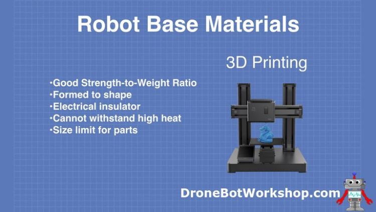
3D printing will allow you to create custom shapes and components for your robot chassis. It also makes it easier to replicate your design, although for larger production runs there are cheaper and better methods, such an injection molding.
There are many materials available to 3D print with but not too many can withstand high temperatures. And the size of most hobbyist 3D printers will limit the size of component you can print, of course you can just divide your design into several smaller components and make something huge.
Cost and availability can be an obstacle, as many of us don’t have 3D printers and the cost of the filament can add up. But if you have, or have access to, a 3D printer you can create a unique design for your robot chassis.
DB1 Chassis
So now that we have examined some chassis materials what one(s) did I use to create the DB1 chassis?

I used both aluminum and acrylic, the aluminum is in the form of channeling and the acrylic in sheets that I use for shelves which will hold the electronics.
Aluminum Channeling
Using aluminum channeling and extrusion is very common in robot designs and there are many varieties to choose from. I considered using extrusion for the ”tower” section of the robot but eventually settled on using channeling for the whole design.
There are many advantages of using aluminum channeling:
- You get all the advantages of using aluminum without needing to machine parts. This allows quick assembly and also let’s those of use who don’t have the tools to cut aluminum to use it as a design material.
- It is readily available, I actually purchased my channeling and components from three different sources.
- It can be easily reconfigured. This is very handy if you are not sure of your design or if you wish to experiment with different configurations.
- Most channeling systems also have other mechanical parts like gears, bearings, shafts and motor mounts. This makes it very easy to get the mechanical bits working quickly.
There are many channeling systems and I don’t see any particular advantage to any of them as they all have similar parts and fasteners. You can also “mix and match” if you are willing to do a bit of drilling.
The channeling system I used is called “Actobotics”.
Actobotics Channeling
The Acrobatics line of channeling and parts is very extensive. It can be used to build robots, CNC machines, 3D printer frames and all sorts of other custom designs.
I chose Actobotics due to its availability. It is distributed by Servocity who can ship it almost anywhere. It also is available at outlets like Robotshop and Sparkfun, as well as from several international distributors.

Another advantage of using Actobotics channeling and components is that it uses standard 6-32 threaded fasteners, which are commonly available. The fasteners in the official Actobotics line use hex-heads, making them very easy to work with.
I should note that I am in Canada and 6-32 hardware is very available here and in the United States. If you are in Europe, Australia, New Zealand or Asia you might want to look at a metric channeling like Lynxmotion instead.
The Actobotics line of components has channeling, extrusion, and a variety of mounts and mechanical parts. They also have some great diagrams for putting together many common assemblies, which made it very easy to order the correct parts.
All Actobotics channeling uses imperial measurements, which is why you’ll find the following diagrams using inches instead of centimeters. The width of the channeling is 1.5 inches and it is sold in increments of 1.5 inch.
DB1 Base Assembly
Here are some diagrams that illustrate how I put together the chassis for DB1 using Actobotics channeling. I’m only showing the chassis ands not the wheels, motors and motor mounts – we will be discussing those in future installments of this series.
Parts List
If you’d like to build an identical chassis you’ll need the following Actobotics parts:
| Part Number | Description | Qty |
| 585450 | 9-inch Channel | 1 |
| 585454 | 12-inch Channel | 3 |
| 585456 | 13.5-inch Channel | 2 |
| 585458 | 15-inch Channel | 2 |
| 585006 | 12” x 9” Pattern Plate | 1 |
| 585004 | 12” x 4.5” Pattern Plate | 1 |
| 585424 | 90° Single Angle Pattern Bracket | 4 |
| 545360 | Side Tapped Pattern Mount C | 10 |
| 632106 | 6-32 x 0.25” Socket-Head Machine Screws | 80 |
| 632108 | 6-32 x 0.3125” Socket-Head Machine Screws | 20 |
| Sourced Locally | 6-32 Nuts | 28 |
The following diagrams will guide you through the assembly:
1 – Base Frame

This is the bottom assembly, consisting of two 12” channels and two 13.5” channels.
On each end of the 12” channel, you will need to mount a Side Tapped Pattern Mount C with four 6-32 x 0.25 Socket-Head Machine Screws. Use an additional four 6-32 x 0.3125” Socket-Head Machine Screws to fasten the 13.5” channels to the frame.
The 12” channels are spaced 9 inches apart, making the total width 12” as each channel is 1.5” wide.
2 – Bottom Plate

The bottom plate is the 12” x 9” pattern plate. It will be used to support the batteries that will eventually power the robot.
Fasten the bottom plate with eight 6-32 x 0.3125” Socket-Head Machine Screws. You will need to use some 6-32 nuts to hold these in place.
3 – Top Plate

The top plate is going to eventually be used to support a robot arm or, hopefully, two robot arms. If you have no intention of installing an arm you can skip this part.
If you do want to install a top plate fasten the 12” x 4.5” Pattern Plate with four 6-32 x 0.3125” Socket-Head Machine Screws. You will need to use some 6-32 nuts to hold these in place.
4 – Tower Assembly

The tower consists of a 12” channel, a 9” channel and two 15” channels. Each end of the 15” and 9” channels will require a Side Tapped Pattern Mount C, mounted to the channel with four 6-32 x 0.25 Socket-Head Machine Screws per pattern mount.
The 12” channel on top and the 9” channel in the middle are secured using 6-32 x 0.25 Socket-Head Machine Screws, four per connection..
Four 90° Single Angle Pattern Brackets are used to hold the acrylic shelves, which are not shown in the diagram or parts list. The brackets are held in place with -32 x 0.25 Socket-Head Machine Screws and 6-32 nuts.
5 – Mount Tower to Base

The final step is to secure the tower to the base. It is mounted in the center of the base and is held in place with eight 6-32 x 0.3125” Socket-Head Machine Screws, four per side.
Conclusion
If you have followed along you now have a robot chassis, ready for motors and wheels. We will discuss these in the next article.
If you’d like additional information regarding DB1 please subscribe to the DroneBot Workshop newsletter. I will be announcing the availability of additional information in a mailing soon.
Happy building!


Any chance that you could convince Servocity to put together a ‘kit’ – packaging all the parts needed for you standard platform under one part number? Also, a discount against the total cost of the individual parts?
I just discovered that Servocity lets you “create a project” with a parts list, and one gets a 15% discount for doing so. They are asking that I submit a picture and a url – is it ok if I use db1-robot-chassis.jpg and this url? Feel free to contact me directly.
Oops, catch-22! I think that the intend that you submit the project for the discount after you build it; they want an instructables.com link and a “picture of your project”. Sigh.
Rats, read the small print of the project submit and realized that I can not submit a project that is actually your project, that would not be correct.
To attach the bottom plate, you said:
“Fasten the bottom plate with eight 6-32 x 0.3125” Socket-Head Machine Screws. You will need to use some 6-32 nuts to hold these in place.”
I’m confused about this step. The channels facing the ground are on the open side and the bottom plate has holes that are going up and down. How is it possible to join the bottom plate to the channels without some kind of 90 degree connector?
Hi Victor. The channels on both sides (not the front or back) do not have the open end facing down, take a look at some of the images. They are mounted with the open-end facing inward. The screws are passed through the plates and secured by nuts. The plate is only fastened to the sides.
I need to pick up some #6 lock washers the next time I make a trip to the hardware store as I want to use them to make sure that the fasteners hold, I will add them later.
You don’t mention the dimensions of the acrylic shelves. I know this isn’t critical and anything in a range will work (as long as they are 9 inches wide) but I am curious to know the dimensions you chose.
Great project by the way… so many possibilities as it evolves.
Steve
I agree it would be of great help if you could give the exact dimensions of the acrylic shelves. I live in west Africa and it’s pretty difficult to purchase all these parts. So i have chosen to replicate your design exactly. Any mistake in cutting the acrylic would be harmful to me. Thanks.
I am India; I need a contact to bring the parts for DB1 Robot from Canada or USA;
Hello!
I noticed that Servocity sells 6-32 nuts as well. But you only bought the machine screws and not the nuts from Servocity. Could you confirm to me if the following nuts from Servocity are appropriate for the machine screws that you used:
https://www.servocity.com/6-32-nylock-nuts-pack
Thank you very much in advance!
/Danial
Hi Danial
I just used standard 6-32 nuts, which are available at my local hardware store (and probably yours as well if you are in North America, may be harder to find elsewhere). The ones you pointed out are nylock nuts, they will work but you would have some difficulty removing them if you had to reconfigure them in the future.
In short, ANY 6-32 nut will work!
Do you have any calculations of how much weight your full DB1 can withstand?
Hi Sir,
Regarding the physical stability of the chassis including the mounted components in different
positions and corner of DB1, is there any: