Table of Contents


Build an amazing custom remote control system using a controller you likely already have!
Introduction
Video game consoles have been taking over the living rooms and basements of the world for decades now, and along with them come some pretty sophisticated controllers. These devices contain joysticks, pressure-sensitive pushbuttons, as well as an accelerometer and feedback “rumble motor.”
All of this makes them great for defeating aliens or controlling the world. It also can make them great for controlling just about anything. You just need to be able to interface with them.
One of the most popular game consoles was the Sony PlayStation 3. And the controllers that come with the PS3 are ideal for myriads of DIY projects.

Today, we will interface a PS3 controller to an ESP32. Our work will be simplified by using a great library that does pretty well everything for us.
Even if you don’t own a PlayStation 3 (I don’t), you can buy a PS3 controller “clone” for next to nothing. The model I purchased ran me 16 Canadian dollars, which is about 12 US dollars. Considering what you are buying, it is a bargain.
PlayStation 3 Controllers
The Sony PlayStation 3 (PS3) is a video game console that was first released in 2006. It was the third home video game console produced by Sony Computer Entertainment and the successor to the PlayStation 2.

The PS3 controller, also known as the Sixaxis or DualShock 3, was designed as the primary input device for the PS3. It is an evolution of the DualShock design from the PlayStation and PlayStation 2 consoles, with the addition of motion sensing technology. The motion sensing technology lets the controller detect movements in three dimensions, allowing players to control games using physical movements.
PS3 Controller Layout
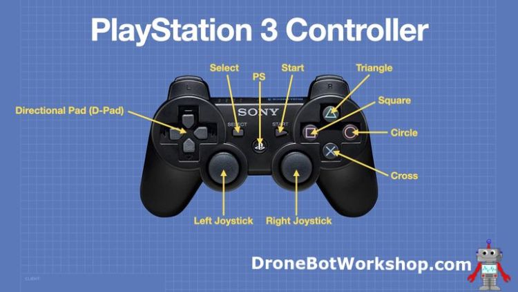
While you can get a variety of PS3-compatible controllers, they all follow the same basic layout. The controller has several buttons and joysticks, each serving a specific function:
- Directional pad (D-pad) – A four-way directional button that is used to navigate menus and make selections.
- Analog sticks – Two thumbsticks used for character movement and camera control. They can be moved in any direction to control the character’s movement or camera angle.
- L1/L2 buttons – Located on the left side of the controller, these buttons are used for various functions, such as aiming or firing weapons, or jumping.
- R1/R2 buttons – Located on the right side of the controller; these buttons are used for similar functions as the L1/L2 buttons, but on the opposite side of the controller.
- Start and Select buttons – These buttons are used to start and pause games or to access the game’s menu.
- Triangle, Circle, Cross, and Square buttons – These buttons are used as the main action buttons in most games. They are used to perform actions such as jumping, attacking, or using items.
- PS button – Located in the center of the controller, this button is used to turn the controller on and off.

Naturally, with our ESP32 designs, we can use the controls in any fashion we choose. However, in some cases, it might be a good idea to consider the controls’ original purpose, especially if you are trying to make a remote control that is intuitive to a gamer.
PS3 Console to Controller Communications
The Sony PlayStation 3 (PS3) controllers use Bluetooth technology for communication between the controller and the game console. The controller sends data to the console regarding its button presses, joystick movements, and other inputs, while the console sends data to the controller to vibrate its built-in motors (known as “rumble”).
Bluetooth uses the 2.4 GHz ISM band, which is an unlicensed frequency range that is available worldwide. This frequency band is divided into several channels, and Bluetooth uses 79 of these channels to transmit and receive data.
The PS3 controller and the console communicate using a protocol known as the Bluetooth HID (Human Interface Device) profile. The HID profile defines how input devices, such as the PS3 controller, should communicate with host devices, such as the PS3 console. Data is transmitted from the controller to the console as HID reports, which contain information about the state of the buttons and joysticks on the controller. The PS3 console returns data to the controller to control the vibration motors.
Pairing the PS3 Console and Controller
To work with the controller, we need to use the ESP32 to emulate the PS3 game console; in other words, we need to “fool” the controller into thinking that it is really communicating with the console.
We will then need to pair the controller and the ESP32 in the same fashion that it pairs with the console. We do that by using the console’s MAC (Media Access Control) address, which is held in the controller in nonvolatile memory.
The MAC address is a unique identifier assigned to each Bluetooth device. It is used to identify the device and allow it to communicate with other Bluetooth devices. When the PS3 console and controller are paired, they exchange their MAC addresses, which are stored on each device. This allows the devices to recognize each other.
So the console stores the controller MAC addresses, and the controller holds the console address. The controller uses this address to communicate with a specific host console.
So we need to emulate that MAC address to work with the controller.
Getting the Console MAC Address
We’ll need the controller’s MAC address to pair it with the ESP32. One way we can do that is to use a tool called the Sixaxis Pair Tool.
The Sixaxis Pair Tool is a utility that facilitates the synchronization of Bluetooth addresses between gamepads and mobile devices. It’s a very simple utility that allows you to both display and change the Bluetooth MAC address of your controller.
The utility is freeware; however, it is only available for Microsoft Windows. I have installed it under both Windows 10 and Windows 11, and it works without any issues.
You’ll need to connect the PS3 controller to your Windows computer using a USB cable; one probably came with the controller (mine uses a Mini USB connector on the controller).
The first time you connect the controller to the computer, it will likely need to download and install a few drivers, so let it go ahead and do that.
With the controller connected, just run the Sixaxis Pair Tool. The MAC address of the console should be displayed.

There is also a box that allows you to set your own MAC address. Just fill it out in the “00:00:00:00:00:00” pattern and click Update. You’ll notice that the MAC address displayed in the panel will change to the one you entered.
Be sure to write down the MAC address of the controller after determining what it is. You’ll need that address to make the code work.
ESP32-PS3 Library
To make life easy, there is a wonderful library that handles all the interfacing between the ESP32 and a PS3 Controller. It’s the ESP32-PS3 Library by Jeffrey van Pernis.
This library has a function for every event on the PS3 controller. It comes with several example sketches that you can use to learn its operation.
ESP32-PS3 Library Installation
The easiest way of installing the ESP32-PS3 Library is to use the Library Manager in the Arduino IDE.
Just open your Library Manager and search for “ESP32-PS3”, and it will show up. Use the Install button to add the library to your local library collection.
The library comes with a number of demos, and you should try them out with our controller to get a feel for working with it. You’ll find all the sketches in the Examples section of your Files menu in the Arduino IDE.
BTW, I’m illustrating the examples using the newer Arduino IDE 2.0, which is what I recommend that you use as well. But if you wish, you can also ruin them with IDE version 1.8; they will all work fine.
PS3Demo
If you are only going to run one demo sketch, then run this one. It’s the “Grand Poohbah” of all the examples.
The sketch is all-encompassing and is the best sketch to learn about the library from. It detects every button and control event, both digital and analog (the buttons give back analog values too).
You’ll have to make one modification to the sketch, the MAC address. This is where you need to have the address of your controller, as determined earlier by the Sixaxis Pair Tool.
Head down to the Setup, to line 203, and edit the following line:
|
1 |
Ps3.begin("01:02:03:04:05:06"); |
Change the 6-digit MAC Address to the one your controller has in memory.
After that, you can upload the sketch to your ESP32. When the upload has finished, open your Serial Monitor and turn on your PS3 controller.
Start pressing buttons, if you are paired (it can take a couple of seconds), then you will see the results of your actions on the Serial Monitor.

Using this sketch, you can test almost every aspect of the controller. And you can use bits and pieces of it in your own sketches as well.
PS3Accelerrometer
The PS3 Controller has an internal accelerometer and gyroscope, and this sketch can test both of them.
The sketch is pretty simple and is structured similarly to the first one, with a callback function called “notify” that is called every time data is received from the controller.
In this case, the callback gets the data from the accelerometer and then prints it to the serial monitor. There is also code that is remarked out for displaying gyroscope data as well.
This sketch can be viewed on either the Serial Monitor or Serial Plotter. Load it up, connect it to the controller, and give both the monitor and plotter a try.

A great example if you are trying to make an animated display remote or some sort of “real life” game.
PS3Rumble
This demo sketch works differently from the previous ones in that it sends data to the controller instead of receiving it.
The sketch activates the two internal “rumble” motors. It calls them within the loop and just repeats a rumble sequence.
Load it up and watch (or feel) it in action! It’s an interesting form of tactical feedback that you might be able to incorporate into one of your own designs.
Controlling I/O Devices
So now that we have installed our library and tried out a few sample sketches let’s see how we can use it to control actual physical devices with our PS3 controller.
I will be building these on a platform that I call my “robot car developer’s base,” which is essentially a 2-wheel robot car kit with a power supply, motor driver, solderless breadboard, and a few prototyping accessories. Check out the video for more details.

I’ll be adding peripherals to the ESP32 and controlling them with the PS3 controller. Eventually, we will have built an odd form of robot car!
You can use these hookups and sketches to build a custom remote control project of your own.
Multiple LEDs
The first experiment we will set up is three LEDs. Remember, the LEDs simply represent output devices; they could just as easily be relays or solid-state switches.

We will control the three LEDs using the buttons on the right side of the controller, the ones with the shapes on them. Each of the LEDs will be controlled in a different fashion:
- LED 1 will be momentary. If you press the Cross button down, it will illuminate, release the button, and the LED will be extinguished.
- LED 2 will be a toggle. Pressing the Triangle button once will turn it on, and pressing it again will turn it off.
- LED 3 is controlled by two push buttons. The Square button will turn it on, while the Circle button will turn it off.
You can use these three examples as the basis for your own custom code.
LED Hookup
We are going to hook up the LEDs to the ESP32 as follows:

I used 220 ohm dropping resistors for each LED, but any value from 100 to 470 ohms would work.
You can use almost any ESP32 module for this and all the other experiments. Make sure to check the pinout diagram for your module, as it may not be the same as the one I have illustrated here.
PS3 LED Control Code
Now we come to the sketch we will use for our PS3 LED controller.
|
1 2 3 4 5 6 7 8 9 10 11 12 13 14 15 16 17 18 19 20 21 22 23 24 25 26 27 28 29 30 31 32 33 34 35 36 37 38 39 40 41 42 43 44 45 46 47 48 49 50 51 52 53 54 55 56 57 58 59 60 61 62 63 64 65 66 67 68 69 70 71 72 73 74 75 76 77 78 79 80 81 82 83 84 85 86 87 88 89 90 91 92 93 |
/* ESP32 PS3 Controller - LED Control Test esp32-ps3-led.ino Control three LEDs with PS3 Controller LED Hookup - LED1=4 LED2=16 LED3=15 Requires ESP32-PS3 Library - https://github.com/jvpernis/esp32-ps3 DroneBot Workshop 2023 https://dronebotworkshop.com */ // Include PS3 Controller library #include <Ps3Controller.h> // Define LED Pins #define LED1_PIN 4 #define LED2_PIN 16 #define LED3_PIN 15 // Variables to hold LED states bool led1State = false; bool led2State = false; bool led3State = false; // Callback Function void notify() { // Cross button - LED1 momentary control if (Ps3.event.button_down.cross) { Serial.println("Cross pressed"); led1State = true; digitalWrite(LED1_PIN, led1State); } if (Ps3.event.button_up.cross) { Serial.println("Cross released"); led1State = false; digitalWrite(LED1_PIN, led1State); } // Triangle Button - LED2 toggle control if (Ps3.event.button_down.triangle) { Serial.println("Triangle presssed"); led2State = !led2State; digitalWrite(LED2_PIN, led2State); } // Square Button - LED3 on if (Ps3.event.button_down.square) { Serial.println("Square pressed"); led3State = true; digitalWrite(LED3_PIN, led3State); } // Circle Button - LED3 off if (Ps3.event.button_down.circle) { Serial.println("Circle pressed"); led3State = false; digitalWrite(LED3_PIN, led3State); } } // On Connection function void onConnect() { // Print to Serial Monitor Serial.println("Connected."); } void setup() { // Setup Serial Monitor for testing Serial.begin(115200); // Define Callback Function Ps3.attach(notify); // Define On Connection Function Ps3.attachOnConnect(onConnect); // Emulate console as specific MAC address (change as required) Ps3.begin("00:00:00:00:00:00"); // Set LED pins as outputs pinMode(LED1_PIN, OUTPUT); pinMode(LED2_PIN, OUTPUT); pinMode(LED3_PIN, OUTPUT); // Print to Serial Monitor Serial.println("Ready."); } void loop() { if (!Ps3.isConnected()) return; delay(2000); } |
We start by including the PS3 Controller library.
Next, we define the pins used for the three LEDs and some booleans to hold their state (true will indicate “on”).
Next is the “notify” callback function. We’ll get to that in a moment, but first, we will jump down and look at the Setup.
In Setup, we begin by setting up our Serial Monitor, which we will use for testing and troubleshooting.
Next, we define the callback and on-connect functions. We also define the MAC address that we will be emulating, so this is where you’ll need to edit the code to work with your controller.
Finally, we set the LED pins as outputs and print “Ready” to the serial monitor.
Now let’s go back to the callback function, called “notify”. This function is run every time data is received from the controller, and it contains the bulk of our code.
We start with LED1, controlled by the Cross button. There are two events we monitor:
- button_down – If we get a button_down event, we turn on the LED.
- button_up – This means the button was released, so we extinguish the LED.
Next, we move to LED2, which will be toggled using the Triangle button.
Unlike the previous example, we are only interested in the Triangle buttons button_down event. Exert time we receive this event, we flip the value of the boolean led2State, which we then use to control the LED. The result is that the LED will toggle every time the button is pressed.
Finally, LED3. It is controlled by two buttons, the Square turns it on while the Circle turns it off.
In both cases, we just monitor for the button_down event from those two buttons and set the LED accordingly.

Load up the sketch and watch the three LEDs. You should be able to control them using the four buttons on the PS3 controller.
RGB LED
We’ll hook a standard RGB LED to our ESP32 and control it with a few of the front push buttons on the controller. Each pushbutton will control a single color on the RGB LED, and the pressure you exert upon the button will control the intensity of the color, as the buttons return analog values as well as digital ones.

If you want to get finer control over the LED segment brightness, try using a joystick instead of a push button.
RGB LED Hookup
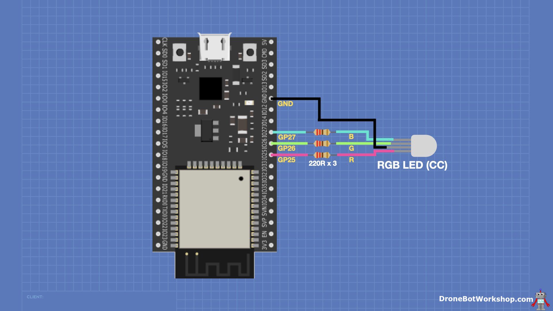
The hookup for our RGB LED is similar to that of the three discrete LEDs we worked with in the last experiment. Once again, I used 220-ohm resistors as dropping resistors, but anything around that value will work.
The LED is a common-cathode RGB LED. In my demo, I used a big 10mm unit, but any common-cathode RGB LED will work.
If you don’t have an RGB LED, you could also just use three discrete LEDs, preferably a red, green, and blue one!
PS3 RGB LED Code
Our sketch will need to get the values from each switch and use them as PWM values for the LED segments.
|
1 2 3 4 5 6 7 8 9 10 11 12 13 14 15 16 17 18 19 20 21 22 23 24 25 26 27 28 29 30 31 32 33 34 35 36 37 38 39 40 41 42 43 44 45 46 47 48 49 50 51 52 53 54 55 56 57 58 59 60 61 62 63 64 65 66 67 68 69 70 71 72 73 74 75 76 77 78 79 80 81 82 83 84 85 86 87 88 89 90 91 92 93 94 95 96 97 98 99 100 101 102 103 104 105 106 107 108 109 110 111 112 113 114 |
/* ESP32 PS3 Controller - RGB LED Test esp32-ps3-rgb.ino Control Common Cathode RGB LED on ESP32 using PS3 controller RGB LED GPIO Connections - R=25 G=26 B=27 Requires ESP32-PS3 Library - https://github.com/jvpernis/esp32-ps3 DroneBot Workshop 2023 https://dronebotworkshop.com */ // Include PS3 Controller library #include <Ps3Controller.h> // RGB LED Connections const int ledRed = 25; const int ledGreen = 26; const int ledBlue = 27; // LED PWM Properties const int ledFreq = 5000; const int ledResolution = 8; // Define channels for each color const int redChannel = 0; const int greenChannel = 1; const int blueChannel = 2; // Variables for LED PWM values int redPWM = 0; int greenPWM = 0; int bluePWM = 0; // Callback Function void notify() { // Shoulder & Trigger button changes for RGB LED // Set RGB values based upon analog button values if (abs(Ps3.event.analog_changed.button.l1)) { // Left Shoulder - Red redPWM = int(Ps3.data.analog.button.l1); } if (abs(Ps3.event.analog_changed.button.l2)) { // Left Trigger - Green greenPWM = int(Ps3.data.analog.button.l2); } if (abs(Ps3.event.analog_changed.button.r2)) { // Right Trigger - Blue bluePWM = int(Ps3.data.analog.button.r2); } // Right Shoulder button turns on all LED segments full, for white if (abs(Ps3.event.analog_changed.button.r1)) { // Right Shoulder - White redPWM = 255; greenPWM = 255; bluePWM = 255; } // Write LED values to RGB LED ledcWrite(redChannel, redPWM); ledcWrite(greenChannel, greenPWM); ledcWrite(blueChannel, bluePWM); // Print to Serial Monitor Serial.print("R = "); Serial.print(redPWM); Serial.print(" - G = "); Serial.print(greenPWM); Serial.print(" - B = "); Serial.println(bluePWM); delay(10); } // On Connection function void onConnect() { // Print to Serial Monitor Serial.println("Connected."); } void setup() { // Setup Serial Monitor for testing Serial.begin(115200); // Define Callback Function Ps3.attach(notify); // Define On Connection Function Ps3.attachOnConnect(onConnect); // Emulate console as specific MAC address (change as required) Ps3.begin("00:00:00:00:00:00"); // Set LED Parameters for each color ledcSetup(redChannel, ledFreq, ledResolution); ledcSetup(greenChannel, ledFreq, ledResolution); ledcSetup(blueChannel, ledFreq, ledResolution); // Attach LED pins to corresponding channels ledcAttachPin(ledRed, redChannel); ledcAttachPin(ledGreen, greenChannel); ledcAttachPin(ledBlue, blueChannel); // Print to Serial Monitor Serial.println("Ready."); } void loop() { if (!Ps3.isConnected()) return; delay(2000); } |
While you might be tempted to use an analogWrite function for this task, there is a better way of using PWM on the ESP32. The ESP32 has several registers dedicated to working with PWM, and they are just perfect for driving LEDs.
We need to set up a few things to use these registers. So in the code, you’ll see variables and constants for things like the PWM frequency (5KHz), the PWM Resolution (8-bits), which pins we are connecting the LED segments to, the PWM values for each channel, and which channels we will be using for each color segment.
Moving down to the Setup function, we set up the three PWM channels and attach them to their respective pins.
Once again, the bulk of the code is in the callback function; the one called “notify”. You’ll see this pattern in almost every sketch we run today!
In notify, we will check whether the buttons have changed value. If they have, then we will get their analog values. As this is already in the range of 0-255 it can be used directly as the PWM value for the color segment.
We gather the three values and then write them to the RGB LED. Simple as that!
Load up the sketch and see if you can control the RGB colors. Try pressing the buttons part-way, to see if you can create dimmer colors. Also, try blending the colors.

It’s fun to play with and can be the basis of a more advanced variable control.
Servo Motor
A servo motor is a very useful device for all sorts of automation projects, and controlling one (or more than one) with a remote control can be very handy.

We will use a joystick (the one on the left side) to control our servo motors’ position. It will be able to move the motor in either direction when you let go of the joystick; the motor will remain in the last position.
I have also set it so that if you move the joystick up, the monitor will “home” to the 90-degree position. You can pick a different position other than 90 degrees to home at if you wish.
Servo Hookup
Hooking up the servo motor is pretty simple, as there is only one data line to deal with.
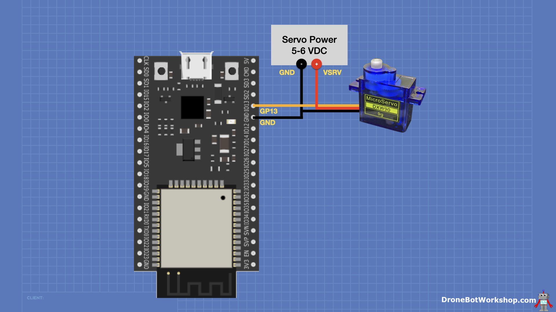
You will need to provide a separate power supply for your servo motor, the SG90 that I used in this experiment requires a power supply of 5 to 6 volts. While it might be tempting to use the 5-volt output from the ESP32, it isn’t a good idea, as the servo motor can induce electrical noise onto the power supply lines. Also, if the servo is restrained, it can consume a large burst of current, potentially overwhelming the power supply on the ESP32.
An excellent power supply for a servo motor is a 6-volt battery pack, such as 4 AA or AAA cells. The SG90 actually works better with 6 volts.
ESP32 PS3 Servo Sketch
We will use the ESP32Servo library, as it doesn’t interfere with the all-important Bluetooth operation like the Arduino Servo library. You may need to install this library from your Library Manager.
|
1 2 3 4 5 6 7 8 9 10 11 12 13 14 15 16 17 18 19 20 21 22 23 24 25 26 27 28 29 30 31 32 33 34 35 36 37 38 39 40 41 42 43 44 45 46 47 48 49 50 51 52 53 54 55 56 57 58 59 60 61 62 63 64 65 66 67 68 69 70 71 72 73 74 75 76 77 78 79 80 81 82 83 84 85 86 87 88 89 90 91 92 93 94 95 96 97 |
/* ESP32 PS3 Controller - Servo Motor Test esp32-ps3-servo.ino Control SG90 Servo on ESP32 using PS3 controller Servo control connected to pin 13 Requires ESP32-PS3 Library - https://github.com/jvpernis/esp32-ps3 DroneBot Workshop 2023 https://dronebotworkshop.com */ // Include required libraries #include <Ps3Controller.h> #include <ESP32Servo.h> // Create servo object Servo srvmtr; // Controller Joystick Values int leftX; int leftY; // Servo Position int servoPos = 90; // Servo Pin #define SERVO_PIN 13 // Callback Function void notify() { // Get Joystick value leftX = (Ps3.data.analog.stick.lx); leftY = (Ps3.data.analog.stick.ly); // Check if joystick was moved upward, indicating return to home (90 degrees) if (leftY < -100) { servoPos = 90; srvmtr.write(servoPos); delay(10); } else { // See if joystick was moved left or right, and in what direction. If moved, move servo in that direction if (leftX < -10 && servoPos < 180) { servoPos++; srvmtr.write(servoPos); delay(10); } if (leftX > 10 && servoPos > 0) { servoPos--; srvmtr.write(servoPos); delay(10); } } // Print to Serial Monitor Serial.print("X value = "); Serial.print(leftX); Serial.print(" - Y value = "); Serial.print(leftY); Serial.print(" - Servo Pos = "); Serial.println(servoPos); } // On Connection function void onConnect() { // Print to Serial Monitor Serial.println("Connected."); } void setup() { // Setup Serial Monitor for testing Serial.begin(115200); // Define Callback Function Ps3.attach(notify); // Define On Connection Function Ps3.attachOnConnect(onConnect); // Emulate console as specific MAC address (change as required) Ps3.begin("00:00:00:00:00:00"); // Attach Servo to pin srvmtr.attach(SERVO_PIN); // Home at 90 degrees srvmtr.write(servoPos); // Print to Serial Monitor Serial.println("Ready."); } void loop() { if (!Ps3.isConnected()) return; delay(2000); } |
At the beginning of the sketch, we call both the PS3 Controller and ESP32Servo libraries.
Next, we define a few integers to hold the X and Y values from the joystick, as well as one for the servo position in degrees. We also define the pin that we have connected to the servo control line.
In the Setup, we attach the servo to the object created to represent it, and we home it at the 90-degree position.
And, as with the previous sketches, most of the action takes place in the “notify” function, which is the callback function.
First, we get the X and Y values from the left joystick.
Then we check to see what direction the joystick has moved. We act as follows:
- If it was moved upward, then we send the servo to the 90-degree position.
- If it was moved to the left, then we move the servo to the left by one increment.
- And if it was moved right, then we move the servo right by one increment.
We print it all to the serial monitor and wait for the next callback to be called.

Load the sketch and give it a try. You should be able to position your servo motor using the left joystick on the PS3 controller.
TOF Sensor
In this experiment, we will use a TOF, or “Time of Flight” sensor with the ESP32 and the PS3 controller.

A TOF sensor is a laser distance sensor. It operates on a similar principle to that of an ultrasonic distance sensor, except it uses a light beam instead of high-frequency sound.
The TPF sensor I will be using, the TOF10120, is a popular unit. I have covered it in depth in the article LASER vs Ultrasonic – Distance Sensor Tests, and some of the code I’m using here is borrowed from that article. The TOF10120 is very inexpensive, and it should be very easy to find.
We will establish a threshold distance and use it with the TOF sensor to see if an object is getting too close. If it doesn’t meet the threshold distance, we will activate the “rumble motors” on the controller.
This might have a practical use when guiding a robot using the PS3 controller as a remote control.
TOF Sensor Hookup
The TOF10120 is an I2C device, so hookup is pretty simple.

There are several I2C pins on the ESP32; I’m using the following set:
- SDA – Pin 32
- SCL – Pin 33
The TOF sensor is powered by the ESP32 3.3 volt output.
PS3 ESP32 TOF Code
Here is the sketch we are using to activate the controller’s onboard rumble motors when we get too close to something.
|
1 2 3 4 5 6 7 8 9 10 11 12 13 14 15 16 17 18 19 20 21 22 23 24 25 26 27 28 29 30 31 32 33 34 35 36 37 38 39 40 41 42 43 44 45 46 47 48 49 50 51 52 53 54 55 56 57 58 59 60 61 62 63 64 65 66 67 68 69 70 71 72 73 74 75 76 77 78 79 80 81 82 83 84 85 86 87 88 89 90 91 92 93 94 95 96 97 98 99 100 101 102 103 104 105 106 107 108 109 110 111 112 113 114 115 116 117 118 119 |
/* ESP32 PS3 Controller - TOF Sensor Test esp32-ps3-tof.ino Activate PS3 Controller vibrating motors when TOF distance is less than threshold Requires TOF10120 TOF sensor with I2C connection Requires ESP32-PS3 Library - https://github.com/jvpernis/esp32-ps3 DroneBot Workshop 2023 https://dronebotworkshop.com */ // Include required libraries #include <Ps3Controller.h> #include <Wire.h> // Pins used for I2C bus #define I2C_SDA 32 #define I2C_SCL 33 // Variables for TOF sensor unsigned char ok_flag; unsigned char fail_flag; unsigned short lenth_val = 0; unsigned char i2c_rx_buf[16]; unsigned char dirsend_flag = 0; // TOS Sensor distcnce int tofDist = 0; // Threshold distance in mm #define MIN_DIST 125 // Callback Function void notify() { } // On Connection function void onConnect() { // Print to Serial Monitor Serial.println("Connected."); } // Read the TOF Sensor void sensorTOFRead(unsigned char addr, unsigned char* datbuf, unsigned char cnt) { unsigned short result = 0; // step 1: instruct sensor to read echoes Wire.beginTransmission(82); // transmit to device #82 (0x52) // the address specified in the datasheet is 164 (0xa4) // but i2c adressing uses the high 7 bits so it's 82 Wire.write(byte(addr)); // sets distance data address (addr) Wire.endTransmission(); // stop transmitting // step 2: wait for readings to happen delay(1); // datasheet suggests at least 30uS // step 3: request reading from sensor Wire.requestFrom(82, cnt); // request cnt bytes from slave device #82 (0x52) // step 5: receive reading from sensor if (cnt <= Wire.available()) { // if two bytes were received *datbuf++ = Wire.read(); // receive high byte (overwrites previous reading) *datbuf++ = Wire.read(); // receive low byte as lower 8 bits } } // Get distance from TOF sensor int readTOFDistance() { sensorTOFRead(0x00, i2c_rx_buf, 2); lenth_val = i2c_rx_buf[0]; lenth_val = lenth_val << 8; lenth_val |= i2c_rx_buf[1]; delay(300); return lenth_val; } int serial_putc(char c, struct __file*) { Serial.write(c); return c; } void setup() { // Setup Serial Monitor for testing Serial.begin(115200); // Define Callback Function Ps3.attach(notify); // Define On Connection Function Ps3.attachOnConnect(onConnect); // Emulate console as specific MAC address (change as required) Ps3.begin("00:00:00:00:00:00"); // Start Wire library for I2C Wire.begin(I2C_SDA, I2C_SCL); // Print to Serial Monitor Serial.println("Ready."); } void loop() { // Read TOF sensor tofDist = readTOFDistance(); Serial.print("D = "); Serial.println(tofDist); if (Ps3.isConnected()) { if (tofDist < MIN_DIST) { // Object is below threshold Ps3.setRumble(100.0); } else { Ps3.setRumble(0.0); } } delay(500); } |
Much of the code for this sketch was taken from the code I used in the earlier article. Essentially, it gets the data from the I2C connection and formats ist for display.
Unlike the other sketches, this one runs in the Loop. Although I have defined the callback function, it actually isn’t necessary, as this time we are not expecting data back from the controller.
You can change the threshold distance if you like, I set mine as 125mm, which worked well for my experiments.
Load the code onto the EWSP32, connect to the PS3 controller, and move an object in front of the sensor. You should feel the controller rumble if the object is closer than the threshold distance.

This is a unique and great method of getting feedback, which you can probably think of a few uses for.
DC Motors
Next, we will hook up two DC motors with a dual H-Bridge driver. In this case, I have the motors mounted on a small “robot car” base, so we are actually building a working toy!

The motors will be controlled using the PS3 controller’s other joystick, and using the joystick, we can move the car around and control its speed and direction.
I’m using my favorite H-Bridge controller, the MOSFET-based TB6612FNG. I have used this in many projects, it’s compatible with the L298N, but it outperforms it.
DC Motor Hookup
You’ll need a power supply suitable for your motors, again don’t share a power supply between the motors and the ESP32. I’m using two 18650 batteries in series to get about 7.4 volts, which works well with those little “yellow” robot car motors. A 6-volt battery pack using AA cells is also a good power source for the motors.
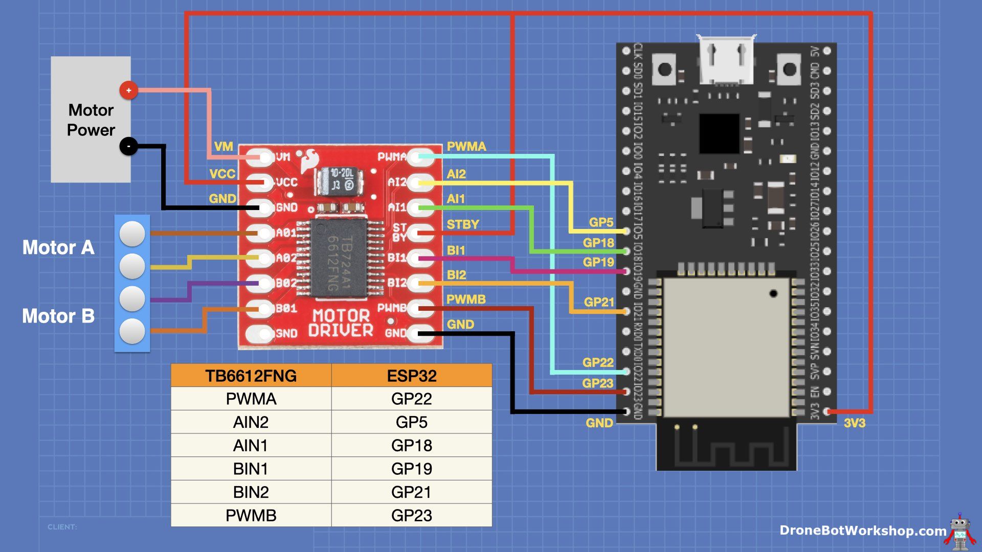
The input lines for the motor driver are all connected to the ESP32, see the chart and wiring diagram for details. The STBY, or “standby,” line must be held HIGH to enable the motor driver.
ESP32 PS3 DC Motor Sketch
Here is the sketch we will use to control our DC motors using a PlayStation 3 controller.
|
1 2 3 4 5 6 7 8 9 10 11 12 13 14 15 16 17 18 19 20 21 22 23 24 25 26 27 28 29 30 31 32 33 34 35 36 37 38 39 40 41 42 43 44 45 46 47 48 49 50 51 52 53 54 55 56 57 58 59 60 61 62 63 64 65 66 67 68 69 70 71 72 73 74 75 76 77 78 79 80 81 82 83 84 85 86 87 88 89 90 91 92 93 94 95 96 97 98 99 100 101 102 103 104 105 106 107 108 109 110 111 112 113 114 115 116 117 118 119 120 121 122 123 124 125 126 127 128 129 130 131 132 133 134 135 136 137 138 139 140 141 142 143 144 145 146 147 148 149 150 151 152 153 154 155 156 157 158 159 160 161 162 163 |
/* ESP32 PS3 Controller - DC Motor Test esp32-ps3-motor.ino Control two DC motors on ESP32 using PS3 controller Requires TB6612FNG H-Bridge (can also use L298N) TB6612FNG Hookup - PWMA=22, AIN2=5, AIN1=18, BIN1=19, BIN2=21, PWMB=23 Requires ESP32-PS3 Library - https://github.com/jvpernis/esp32-ps3 DroneBot Workshop 2023 https://dronebotworkshop.com */ // Include PS3 Controller library #include <Ps3Controller.h> // Define motor driver pins #define PWMA_PIN 22 #define AIN1_PIN 18 #define AIN2_PIN 5 #define PWMB_PIN 23 #define BIN1_PIN 19 #define BIN2_PIN 21 // Define PWM Parameters const int motorFreq = 1000; const int motorResolution = 8; // Define channels for each motor const int motorAChannel = 3; const int motorBChannel = 4; // Variables for Motor PWM values int motorAPWM = 0; int motorBPWM = 0; // Variables for motor direction - true=forward bool motorDir = true; // Variables for joystick values int rightX = 0; int rightY = 0; // Callback Function void notify() { // Get Joystick value rightX = (Ps3.data.analog.stick.rx); rightY = (Ps3.data.analog.stick.ry); //Determine direction from Y axis position if (rightY < 0) { // Direction is forward motorDir = true; } else { // Direction is reverse motorDir = false; } // Convert joystick values to positive 0 - 255 int speedX = (abs(rightX) * 2); int speedY = (abs(rightY) * 2); // Factor in the X axis value to determine motor speeds (assume Motor A is Left motor going forward) if (rightX < -10) { // Motor B faster than Motor A motorAPWM = speedY - speedX; motorBPWM = speedY + speedX; } else if (rightX > 10) { // Motor A faster than Motor B motorAPWM = speedY + speedX; motorBPWM = speedY - speedX; } else { // Control is in middle, both motors same speed motorAPWM = speedY; motorBPWM = speedY; } // Ensure that speed values remain in range of 0 - 255 motorAPWM = constrain(motorAPWM, 0, 255); motorBPWM = constrain(motorBPWM, 0, 255); // Drive the motors moveMotors(motorAPWM, motorBPWM, motorDir); // Print to Serial Monitor Serial.print("X value = "); Serial.print(rightX); Serial.print(" - Y value = "); Serial.print(rightY); Serial.print(" - Motor A = "); Serial.print(motorAPWM); Serial.print(" - Motor B = "); Serial.println(motorBPWM); } // On Connection function void onConnect() { // Print to Serial Monitor Serial.println("Connected."); } // Motor movement function void moveMotors(int mtrAspeed, int mtrBspeed, bool mtrdir) { // Set direction pins if (!mtrdir) { // Move in reverse digitalWrite(AIN1_PIN, HIGH); digitalWrite(AIN2_PIN, LOW); digitalWrite(BIN1_PIN, HIGH); digitalWrite(BIN2_PIN, LOW); } else { // Move Forward digitalWrite(AIN1_PIN, LOW); digitalWrite(AIN2_PIN, HIGH); digitalWrite(BIN1_PIN, LOW); digitalWrite(BIN2_PIN, HIGH); } // Drive motors with PWM ledcWrite(motorAChannel, mtrAspeed); ledcWrite(motorBChannel, mtrBspeed); } void setup() { // Setup Serial Monitor for testing Serial.begin(115200); // Define Callback Function Ps3.attach(notify); // Define On Connection Function Ps3.attachOnConnect(onConnect); // Emulate console as specific MAC address (change as required) Ps3.begin("00:00:00:00:00:00"); // Set motor controller pins as outputs pinMode(PWMA_PIN, OUTPUT); pinMode(PWMB_PIN, OUTPUT); pinMode(AIN1_PIN, OUTPUT); pinMode(AIN2_PIN, OUTPUT); pinMode(BIN1_PIN, OUTPUT); pinMode(BIN2_PIN, OUTPUT); // Set channel Parameters for each motor ledcSetup(motorAChannel, motorFreq, motorResolution); ledcSetup(motorBChannel, motorFreq, motorResolution); // Attach Motor PWM pins to corresponding channels ledcAttachPin(PWMA_PIN, motorAChannel); ledcAttachPin(PWMB_PIN, motorBChannel); // Print to Serial Monitor Serial.println("Ready."); } void loop() { if (!Ps3.isConnected()) return; delay(2000); } |
We define all the connection pins to the motor driver. Once again, we will use the internal PWM registers to control the motor PWM, which sets the motor speeds. We also set it up as 8-bit PWM with a frequency of 1KHz.
We also define a boolean for motor direction. We will always drive both motors in the same direction in this setup.
A couple of other variables hold the joystick values and the motor PWM values.
In the Setup, we define all the connections as outputs, and we set up the two PWM channels and attach them to the PWM pins for each motor.
There is another function defined in the code, moveMotors. This function gets the speed and direction values and moves the two motors accordingly.
As with most of our other sketches, the real action is in the callback function, again called “notify”. In this function, we get the X and Y values for the right joystick. These are used to determine the motor speed and direction, which we pass to the moveMotors function. Finally, we print all the values to the serial monitor and await another callback.
Load it up and watch your motors, or if you are using a robot car base, drive it around. You should see the motors respond in speed and direction to the right joystick.

Obviously, this is a very useful remote control upon which you can design a complete robot car project.
Putting it all together
This final sketch amalgamates all the sketches we have worked with in this section.
|
1 2 3 4 5 6 7 8 9 10 11 12 13 14 15 16 17 18 19 20 21 22 23 24 25 26 27 28 29 30 31 32 33 34 35 36 37 38 39 40 41 42 43 44 45 46 47 48 49 50 51 52 53 54 55 56 57 58 59 60 61 62 63 64 65 66 67 68 69 70 71 72 73 74 75 76 77 78 79 80 81 82 83 84 85 86 87 88 89 90 91 92 93 94 95 96 97 98 99 100 101 102 103 104 105 106 107 108 109 110 111 112 113 114 115 116 117 118 119 120 121 122 123 124 125 126 127 128 129 130 131 132 133 134 135 136 137 138 139 140 141 142 143 144 145 146 147 148 149 150 151 152 153 154 155 156 157 158 159 160 161 162 163 164 165 166 167 168 169 170 171 172 173 174 175 176 177 178 179 180 181 182 183 184 185 186 187 188 189 190 191 192 193 194 195 196 197 198 199 200 201 202 203 204 205 206 207 208 209 210 211 212 213 214 215 216 217 218 219 220 221 222 223 224 225 226 227 228 229 230 231 232 233 234 235 236 237 238 239 240 241 242 243 244 245 246 247 248 249 250 251 252 253 254 255 256 257 258 259 260 261 262 263 264 265 266 267 268 269 270 271 272 273 274 275 276 277 278 279 280 281 282 283 284 285 286 287 288 289 290 291 292 293 294 295 296 297 298 299 300 301 302 303 304 305 306 307 308 309 310 311 312 313 314 315 316 317 318 319 320 321 322 323 324 325 326 327 328 329 330 331 332 333 334 335 336 337 338 339 340 341 342 343 344 345 346 347 348 349 350 351 352 353 354 355 356 357 358 359 360 361 362 363 364 365 366 367 368 369 370 371 372 373 374 375 376 377 378 379 380 381 382 383 384 385 386 387 388 389 390 391 392 393 |
/* ESP32 PS3 Controller Robot Car esp32-ps3-final.ino Control multiple devices with PS3 controller Requires ESP32-PS3 Library - https://github.com/jvpernis/esp32-ps3 DroneBot Workshop 2023 https://dronebotworkshop.com */ // Include required libraries #include <Ps3Controller.h> #include <ESP32Servo.h> #include <Wire.h> // Define LED Pins #define LED1_PIN 4 #define LED2_PIN 16 #define LED3_PIN 15 // Variables to hold LED states bool led1State = false; bool led2State = false; bool led3State = false; // Define motor driver pins #define PWMA_PIN 22 #define AIN1_PIN 18 #define AIN2_PIN 5 #define PWMB_PIN 23 #define BIN1_PIN 19 #define BIN2_PIN 21 // Define motor PWM Parameters const int motorFreq = 1000; const int motorResolution = 8; // Define channels for each motor const int motorAChannel = 3; const int motorBChannel = 4; // Variables for Motor PWM values int motorAPWM = 0; int motorBPWM = 0; // Variables for motor direction - true=forward bool motorDir = true; // Variables for right joystick values int rightX = 0; int rightY = 0; // RGB LED Connections const int ledRed = 25; const int ledGreen = 26; const int ledBlue = 27; // RGB LED PWM Properties const int ledFreq = 5000; const int ledResolution = 8; // Define channels for each RGB LED color const int redChannel = 5; const int greenChannel = 1; const int blueChannel = 2; // Variables for RGB LED PWM values int redPWM = 0; int greenPWM = 0; int bluePWM = 0; // Create servo object Servo srvmtr; // Controller Left Joystick Values int leftX; int leftY; // Servo Position int servoPos = 90; // Servo Pin #define SERVO_PIN 13 // Pins used for I2C bus #define I2C_SDA 32 #define I2C_SCL 33 // Variables for TOF sensor unsigned char ok_flag; unsigned char fail_flag; unsigned short lenth_val = 0; unsigned char i2c_rx_buf[16]; unsigned char dirsend_flag = 0; // TOS Sensor distcnce int tofDist = 0; // Threshold distance in mm #define MIN_DIST 125 // Callback Function void notify() { // Get Left Joystick value leftX = (Ps3.data.analog.stick.lx); leftY = (Ps3.data.analog.stick.ly); // Get Right Joystick value rightX = (Ps3.data.analog.stick.rx); rightY = (Ps3.data.analog.stick.ry); // Check if left joystick was moved upward, indicating return to home (90 degrees) if (leftY < -100) { servoPos = 90; srvmtr.write(servoPos); delay(10); } else { // See if left joystick was moved left or right, and in what direction. If moved, move servo in that direction if (leftX < -10 && servoPos < 180) { servoPos++; srvmtr.write(servoPos); delay(10); } if (leftX > 10 && servoPos > 0) { servoPos--; srvmtr.write(servoPos); delay(10); } } //Determine motor direction from right joystick Y axis position if (rightY < 0) { // Direction is forward motorDir = true; } else { // Direction is reverse motorDir = false; } // Convert joystick values to positive 0 - 255 int speedX = (abs(rightX) * 2); int speedY = (abs(rightY) * 2); // Factor in the X axis value to determine motor speeds (assume Motor A is Left motor going forward) if (rightX < -10) { // Motor B faster than Motor A motorAPWM = speedY - speedX; motorBPWM = speedY + speedX; } else if (rightX > 10) { // Motor A faster than Motor B motorAPWM = speedY + speedX; motorBPWM = speedY - speedX; } else { // Control is in middle, both motors same speed motorAPWM = speedY; motorBPWM = speedY; } // Ensure that speed values remain in range of 0 - 255 motorAPWM = constrain(motorAPWM, 0, 255); motorBPWM = constrain(motorBPWM, 0, 255); // Drive the motors moveMotors(motorAPWM, motorBPWM, motorDir); // Print to Serial Monitor Serial.print("X value = "); Serial.print(rightX); Serial.print(" - Y value = "); Serial.print(rightY); Serial.print(" - Motor A = "); Serial.print(motorAPWM); Serial.print(" - Motor B = "); Serial.println(motorBPWM); // Cross button - LED1 momentary control if (Ps3.event.button_down.cross) { Serial.println("Cross pressed"); led1State = true; digitalWrite(LED1_PIN, led1State); } if (Ps3.event.button_up.cross) { Serial.println("Cross released"); led1State = false; digitalWrite(LED1_PIN, led1State); } // Triangle Button - LED2 toggle control if (Ps3.event.button_down.triangle) { Serial.println("Triangle presssed"); led2State = !led2State; digitalWrite(LED2_PIN, led2State); } // Square Button - LED3 on if (Ps3.event.button_down.square) { Serial.println("Square pressed"); led3State = true; digitalWrite(LED3_PIN, led3State); } // Circle Button - LED3 off if (Ps3.event.button_down.circle) { Serial.println("Circle pressed"); led3State = false; digitalWrite(LED3_PIN, led3State); } // Shoulder & Trigger button changes for RGB LED // Set RGB values based upon analog button values if (abs(Ps3.event.analog_changed.button.l1)) { // Left Shoulder - Red redPWM = int(Ps3.data.analog.button.l1); } if (abs(Ps3.event.analog_changed.button.l2)) { // Left Trigger - Green greenPWM = int(Ps3.data.analog.button.l2); } if (abs(Ps3.event.analog_changed.button.r2)) { // Right Trigger - Blue bluePWM = int(Ps3.data.analog.button.r2); } // Right Shoulder button turns on all LED segments full, for white if (abs(Ps3.event.analog_changed.button.r1)) { // Right Shoulder - White redPWM = 255; greenPWM = 255; bluePWM = 255; } // Write LED values to RGB LED ledcWrite(redChannel, redPWM); ledcWrite(greenChannel, greenPWM); ledcWrite(blueChannel, bluePWM); // Print to Serial Monitor Serial.print("R = "); Serial.print(redPWM); Serial.print(" - G = "); Serial.print(greenPWM); Serial.print(" - B = "); Serial.println(bluePWM); } // On Connection function void onConnect() { // Print to Serial Monitor Serial.println("Connected."); } // Motor movement function void moveMotors(int mtrAspeed, int mtrBspeed, bool mtrdir) { // Set direction pins if (!mtrdir) { // Move in reverse digitalWrite(AIN1_PIN, HIGH); digitalWrite(AIN2_PIN, LOW); digitalWrite(BIN1_PIN, HIGH); digitalWrite(BIN2_PIN, LOW); } else { // Move Forward digitalWrite(AIN1_PIN, LOW); digitalWrite(AIN2_PIN, HIGH); digitalWrite(BIN1_PIN, LOW); digitalWrite(BIN2_PIN, HIGH); } // Drive motors with PWM ledcWrite(motorAChannel, mtrAspeed); ledcWrite(motorBChannel, mtrBspeed); } // Read the TOF Sensor void sensorTOFRead(unsigned char addr, unsigned char* datbuf, unsigned char cnt) { unsigned short result = 0; // step 1: instruct sensor to read echoes Wire.beginTransmission(82); // transmit to device #82 (0x52) // the address specified in the datasheet is 164 (0xa4) // but i2c adressing uses the high 7 bits so it's 82 Wire.write(byte(addr)); // sets distance data address (addr) Wire.endTransmission(); // stop transmitting // step 2: wait for readings to happen delay(1); // datasheet suggests at least 30uS // step 3: request reading from sensor Wire.requestFrom(82, cnt); // request cnt bytes from slave device #82 (0x52) // step 5: receive reading from sensor if (cnt <= Wire.available()) { // if two bytes were received *datbuf++ = Wire.read(); // receive high byte (overwrites previous reading) *datbuf++ = Wire.read(); // receive low byte as lower 8 bits } } // Get distance from TOF sensor int readTOFDistance() { sensorTOFRead(0x00, i2c_rx_buf, 2); lenth_val = i2c_rx_buf[0]; lenth_val = lenth_val << 8; lenth_val |= i2c_rx_buf[1]; delay(300); return lenth_val; } int serial_putc(char c, struct __file*) { Serial.write(c); return c; } void setup() { // Setup Serial Monitor for testing Serial.begin(115200); // Define Callback Function Ps3.attach(notify); // Define On Connection Function Ps3.attachOnConnect(onConnect); // Emulate console as specific MAC address (change as required) Ps3.begin("00:00:00:00:00:00"); // Set LED pins as outputs pinMode(LED1_PIN, OUTPUT); pinMode(LED2_PIN, OUTPUT); pinMode(LED3_PIN, OUTPUT); // Set RGB LED Parameters for each color ledcSetup(redChannel, ledFreq, ledResolution); ledcSetup(greenChannel, ledFreq, ledResolution); ledcSetup(blueChannel, ledFreq, ledResolution); // Attach RGB LED pins to corresponding channels ledcAttachPin(ledRed, redChannel); ledcAttachPin(ledGreen, greenChannel); ledcAttachPin(ledBlue, blueChannel); // Attach Servo to pin srvmtr.attach(SERVO_PIN); // Home at 90 degrees srvmtr.write(servoPos); // Set motor controller pins as outputs pinMode(PWMA_PIN, OUTPUT); pinMode(PWMB_PIN, OUTPUT); pinMode(AIN1_PIN, OUTPUT); pinMode(AIN2_PIN, OUTPUT); pinMode(BIN1_PIN, OUTPUT); pinMode(BIN2_PIN, OUTPUT); // Set channel Parameters for each motor ledcSetup(motorAChannel, motorFreq, motorResolution); ledcSetup(motorBChannel, motorFreq, motorResolution); // Attach Motor PWM pins to corresponding channels ledcAttachPin(PWMA_PIN, motorAChannel); ledcAttachPin(PWMB_PIN, motorBChannel); // Start Wire library for I2C Wire.begin(I2C_SDA, I2C_SCL); // Print to Serial Monitor Serial.println("Ready."); } void loop() { // Read TOF sensor tofDist = readTOFDistance(); Serial.print("D = "); Serial.println(tofDist); if (Ps3.isConnected()) { if (tofDist < MIN_DIST) { // Object is below threshold Ps3.setRumble(100.0); } else { Ps3.setRumble(0.0); } } delay(500); } |
The only change necessary was to move the channel used for the red segment of the RGB LED. The original channel, channel 0, conflicts with the ESP32Servo library. I moved the red to channel 5 to resolve this conflict.
Otherwise, it’s just every section of every sketch rolled into one.
It’s an example of how to make a custom remote control using an ESP32 and a PS3 controller.
Conclusion
A Sony PlayStation 3 Controller is a pretty sophisticated yet inexpensive device designed to blast aliens, drive racecars and move football players. And using the ESP32-PS3 Library, we can repurpose the controller to become a super remote control, capable of controlling anything that you can connect to an ESP32.
From moving a robot, controlling holiday lights, manipulating an animated display or just having the coolest TV remote control on the block – the applications are almost unlimited for this powerful combo.
And you might even have everything you need to get started already. Even if you don’t have a few controllers on hand, you can pick them up for next to nothing.
So up your controller game – move from controlling video pixels to controlling the real world. Nothing can stop you now!
Parts List
Here are some components that you might need to complete the experiments in this article. Please note that some of these links may be affiliate links, and the DroneBot Workshop may receive a commission on your purchases. This does not increase the cost to you and is a method of supporting this ad-free website.
PS3 Controller (clone) – Amazon
ESP32 DEVKIT C – Digikey
Resources
Code used in this article – All the sketches in a nice ZIP file, ready to use!
ESP32-PS3 Library – The ESP32 PS3 Library on GitHub
SixAxis Pair Tool – Download the SixAxis Pair Tool for Microsoft Windows.


Another really great tutorial. Thanks for the inspiration, Bill.
Started this project, but unfortunately, for me, the Sixaxis Pair tool doesn’t seem to recognise either of the two (new) PS3 controllers (from different manufacturers). Sixaxis seems to connect ok (so I assume the drivers are all ok), but it just reports ‘searching…’ continuously.
Same here, two different controllers. Sixaxis Pair tool, No device Fund. I just need the MAC address, correct? Reminds me of trying to get WiiPi to work, without success.
I borrowed a pukka Sony Controller and that works just fine. So I’m considering dumping the lookalike and buying a proper Sony one.
Aww that’s a bummer. I have a Sony controller and have had no problems on the controller end. On the other hand when I tried upgrading to Arduino v2.0 EVERYTHING broke. I couldn’t get anything on to any board.. but that’s another matter. Much as I don’t like the company, you’re probably best using actual Sony remotes for this.
I made sure I got an OEM controller and the Pair Tool worked! Looking forward to starting with these examples.
I got an ‘Base MAC must be a unicast MAC’ error so, after a little research, I changed the MAC address in SixaxisPair to 48:22:33:44:55:66 and it worked
Hello Bill
Thank you for these Video.
I get an error for #include
Whén I change it to #include it works
Is this Ok ?
Kindly regards
Excellent Tutorial. I had quick test with my PS3 controllers (two) and it seems accelerometer /gyroscope does not work on both controllers and only getting ” -4 0 -132 0 ” in the serial monitor but all other functions are working ok. Do you think they have dead DOA or missing accelerometer /gyroscope ? or do i have do some trick to enable accelerometer /gyroscope to work? Thank you for suggestions.
Great project the possibilities are endless. Thank you
Started this project, but unfortunately, for me, the Sixaxis Pair tool doesn’t seem to recognise either of the two (new) PS3 controllers (from different manufacturers). Sixaxis seems to connect ok (so I assume the drivers are all ok), but it just reports ‘searching…’ continuously.
When running any of the PS3 examples I the Serial Monitor shows;
Ready
Then when I start the PS3 controller I get;
ASSERT_WARN(21 16), in lc_task.c at line 2048
Has anyone else had this problem and managed to find a solution?
Any help appreciated.
Same here, would love to know what it means.
Are you guys using plain vanilla esp32’s? The S2 has no bluetooth and the C3 doesn’t have “classic” bluetooth, only BLE, which is different apparently. I’m not sure about the S3…
I’ve tried several Vanilla Esp32s, and a Adafruit ESP32 Huzzahs, to no avail 🙁
Same here… is there a already solution?
Receiving error:
c:\Users\Doug\Documents\Arduino\libraries\PS3_Controller_Host\src\Ps3Controller.cpp:3:10: fatal error: esp_bt_main.h: No such file or directory
#include <esp_bt_main.h>
^~~~~~~~~~~~~~~
compilation terminated.
exit status 1
I’m using Arduino IDE 2.0.4 and Adafruit QT Py ESP32-S2
Any help would be appreciated. I really want to use my PS3 controller!
thanks.
dt
same issue, re-selecting the right esp32 “Board” option in Arduino helped me
I have built an ESP32 based controller for flying the Tello drone.
See: ESP32 Tello Drone Controller
I wonder if I can interface a PS3 or PS4 game controller to my controller via BlueTooth? I happen to have a genuine Sony PS4 controller on my workshop bench. But I am using an AdaFruit ESP32 Huzzah dev board to make thinks work and Bill uses some other ESP32 board variety in his workshop treatment. Anyone have experience to make Bill’s demo work and if so what brand ESP32 and what PS3 or PS4 controller was used to make that happen?
By following Bill’s great tutorial,I’ve had success using an Adafruit ESP 32 Feather Huzzah, an AZ Node MCU ESP32 and a vanilla, unbranded ESP32 Dev board. All worked perfectly but ONLY when I used a genuine Sony PS3 (I couldn’t get an unbranded PS3 from Amazon to work at all).
I’ve been playing with the ESP32-PS3 library. I’d like to get some ideas on how to make the motors gradually accelerate and decelerate in a smooth way. For example when moving from full speed (joystick all the way forward) to zero (joystick centered) the motors stop instantaneously. I’d like to make this action gradual. Any ideas?
Thanks!
Hi, I am trying to pair the PS3 controller, but cannot get the Six Axis Pairing Tool to get the MAC address. Keep getting the following error.
“No device found…”
I had to resort to using a genuine Sony PS3 in order to get SixAxis tool to work, PS3 clone showed the same message you have.
I was not able to get it work with Windows 11, but I dug out my old Windows 10 laptop and it worked fine and gave me the MAC’s of the PS3 clones I purchased. They all had the same one and I was able to change them to unique ones. Making Mini R2’s for my grandkids and this was the final hurdle for the control system. Thanks for your post and link to the utilities. Huge help!
Hello, so if you can get the mac code from the ps3 clone controllers?
FYI Some clone ps3 controllers actually show as an xbox controller, which wont work with 6axis but will work with xbox code.
After giving up on clones, I purchased a “Sony” controller. I am able to read and change the MAC address with the Sixaxis Pair Tool. I changed the MAC address to match the ESP 32. I am using a ESP32 DEV Module running Windows 10. When I upload my sketch, the controller works as long as the board is connected to the laptop. When I disconnect the USB cable and power the ESP32 with external power, the controller will not connect.
I tried to run the Ps3-esp32 demo and the demo gave out a whole bunch of compilation errors such as:
undefined reference to
‘esp_spp_deinit’
‘esp_spp_init’
‘esp_spp_start_srv’
‘L2CA_Deregister’
‘L2CA_ConfigReg’
‘ps3_spp_callback’
and many more. All I did was to compile the code as downloaded, am I missing something?
Thanks in advance for your help.
K.C. Huang
Great information! I’m using a PS3 controller connecting to an ESP32 to drive my robot and it works fine except the controller times out and disconnects after perhaps 3 minutes of inactivity. To reconnect I have to power cycle the ESP32. Does anyone know of a way to jog the controller using code to keep it from timing out, perhaps something using Ps3.setRumble?
?
Great Article abd very inspirational.
I wonder if it is possible to combine the PS3 controller as above and utilize the D+ D- pins on an ESP32-S3 to cable connect the controller to achieve multiple functions, i.e set the BLT MAC address for out of the box controllers (change unicast preset) and continue to use the controller in case of low battery or simply being hard wired?